Sensor panel #2
Click image to jump to specific module

Contains:
- Microphone
- 128×64 OLED display
- DHT11 humidity sensor
- NTC thermistor
- Piezo electric buzzer
- DC motor driver
Arduino examples: Github | TE-SP02-B
This side panel is a combination of sensors with display and motor driver as a bonus. Can be used to detect sound, room temperature, visualize data or alert with buzzer. Motor driver allows to control it manually or digitally using TotemDuino.
Power
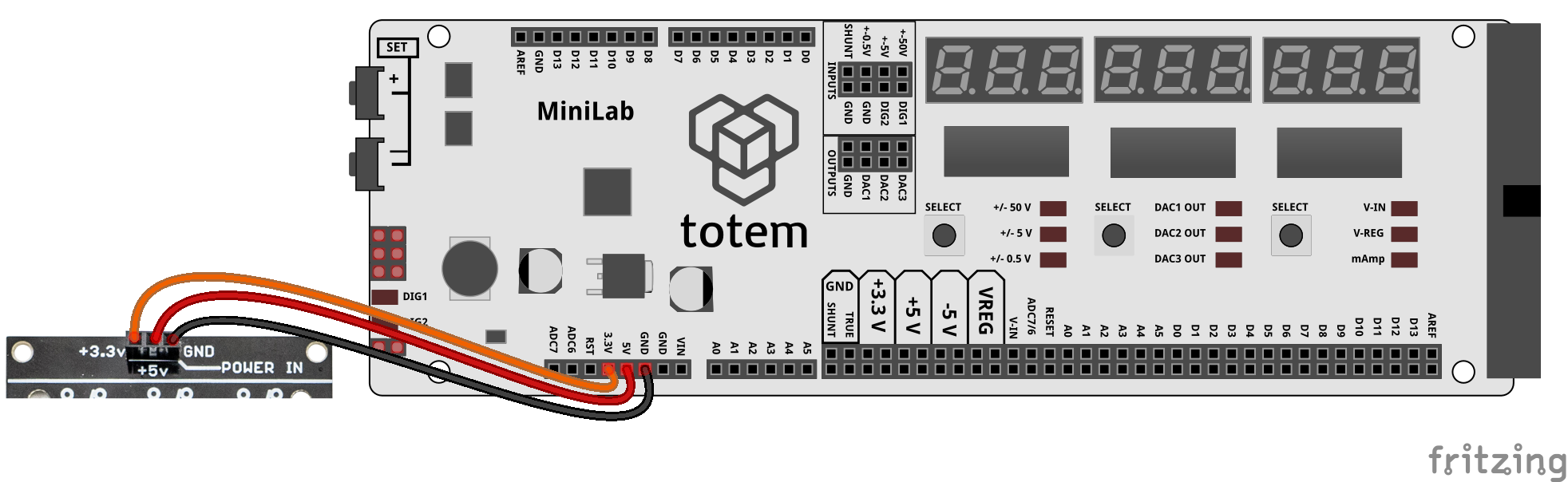
On the top of the board there is (POWER IN) pin header to supply power to side panel components. Some of them requires certain voltage to operate, but otherwise they’re fully isolated from one another, and can be used independently.
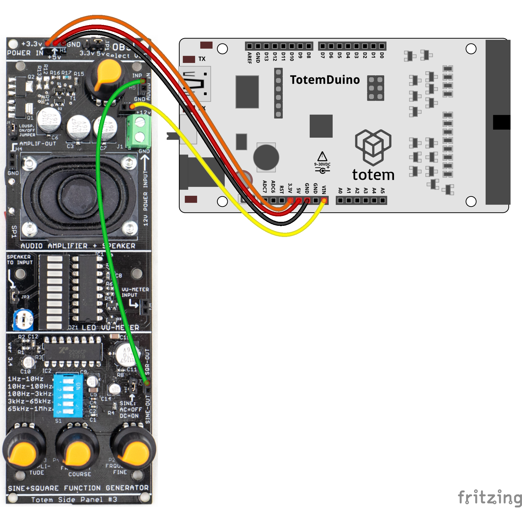
Power up side panel:
Side panel requires power (3.3V, 5V) for certain modules to work. It does not have its own voltage regulator so typically, regulated voltage has to be sourced from TotemDuino or LabBoard. Recommended to plug in all 3 wires as some modules use different voltages.
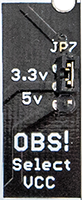
Select logic voltage level:
Side panel contains logic level voltage (VCC) select for digital signals to work either at 3.3 or 5 Volt. Marked OBS! (Observe!).
By moving JP7 jumper up or down - you can select between 3.3V and 5V. This is useful if you have some components that are 3.3 Volt only (could be damaged if used with 5V). In that case place jumper on 3.3V position and use side panel pins safely. It’s important to have the same logic level as the controller board (e.g., TotemDuino), for best results.
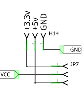
Places where selected voltage (VCC) is used:
- Display power and logic
- Humidity sensor power and logic
- NTC reference voltage
- DC motor control buttons
Microphone and buzzer modules are always using +5v to power their circuit.
Microphone
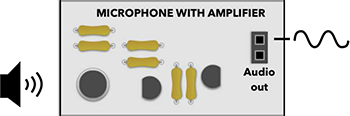
Microphone module with integrated amplifier. Outputs analog audio signal in 0..5V range.
Pin header:
- pin 1, 2 - microphone signal output
Info:
- Arduino example: Sound alarm.
Power:
- Uses +5v POWER IN for amplification circuit.
| Schematic | Experiment |
|---|---|
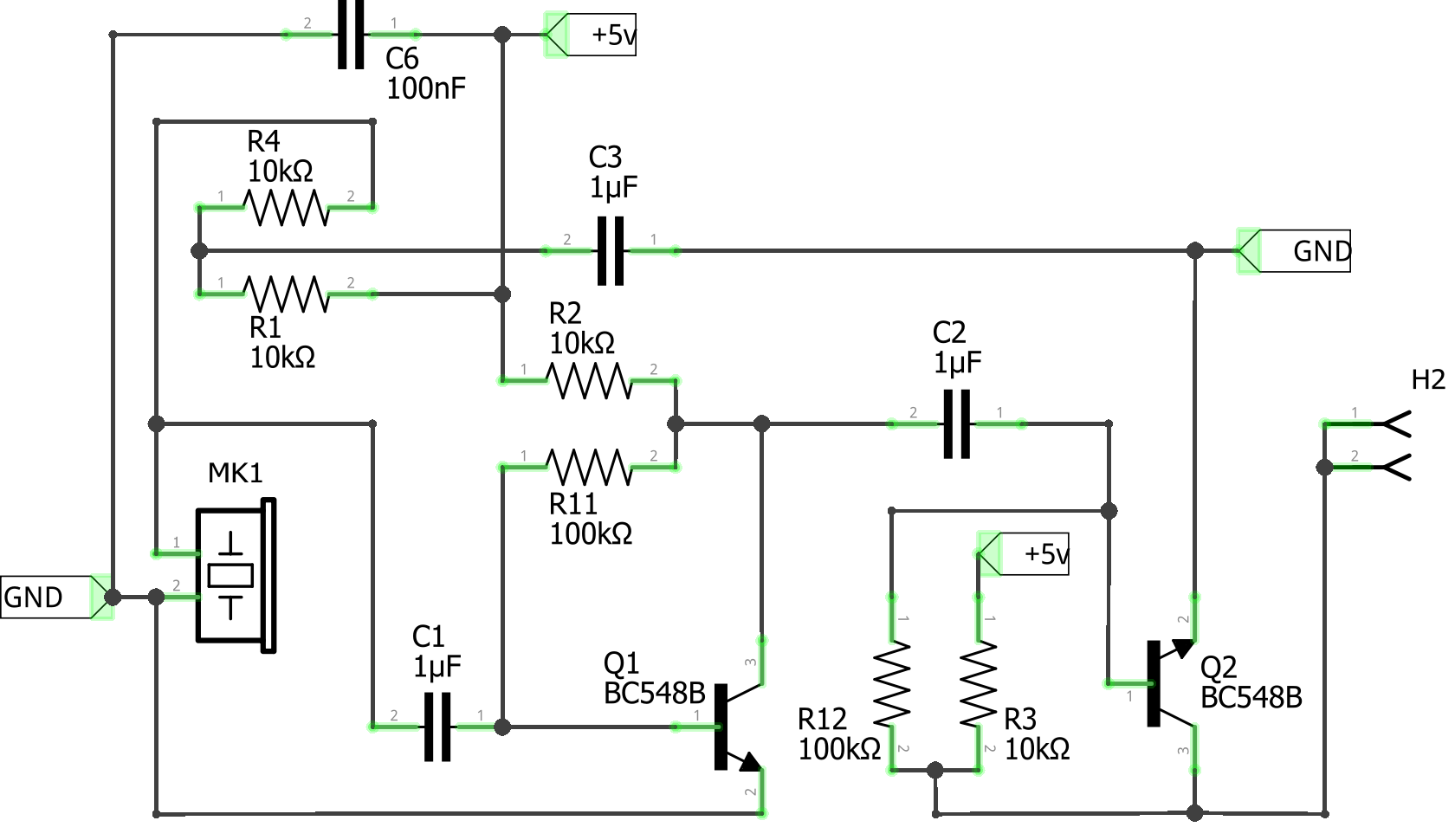 |
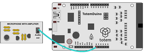 Read microphone using TotemDuino. |
Display
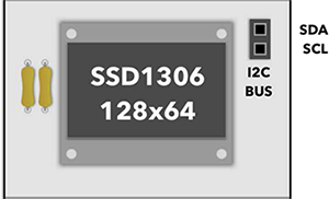
Monochrome I2C display to show text and simple graphics. Uses SSD1306 driver with 0x3C I2C address.
Pin header:
- pin 1 - data signal SDA
- pin 2 - clock signal SCL
Info:
- Arduino library: Adafruit SSD1306.
- Arduino example: Display test.
- Integrated pull-up resistors for I2C communication.
Power:
- Uses VCC to power display. Works with both 3.3 or 5 V supply voltages.
| Schematic | Experiment |
|---|---|
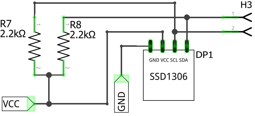 |
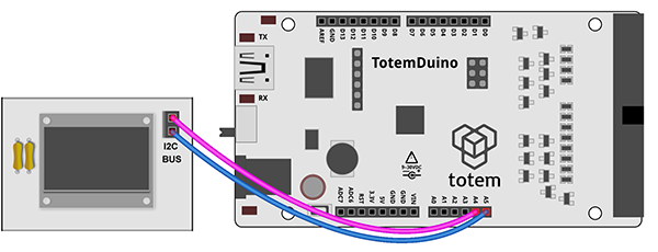 Control display using TotemDuino. |
Humidity sensor
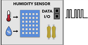
Digital temperature and humidity sensor DHT11. Uses 1-wire protocol to communicate with a microcontroller.
Pin header:
- pin 1, 2 - 1-wire data signal
Info:
- Arduino library: DHT sensor library.
- Arduino example: Temperature and humidity read.
- Measures temperature in Celsius and humidity in percentage.
Power:
- Uses VCC to power sensor. Works with both 3.3 or 5 V supply voltages.
| Schematic | Experiment |
|---|---|
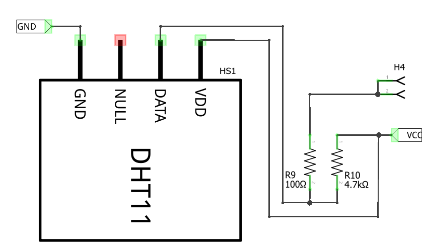 |
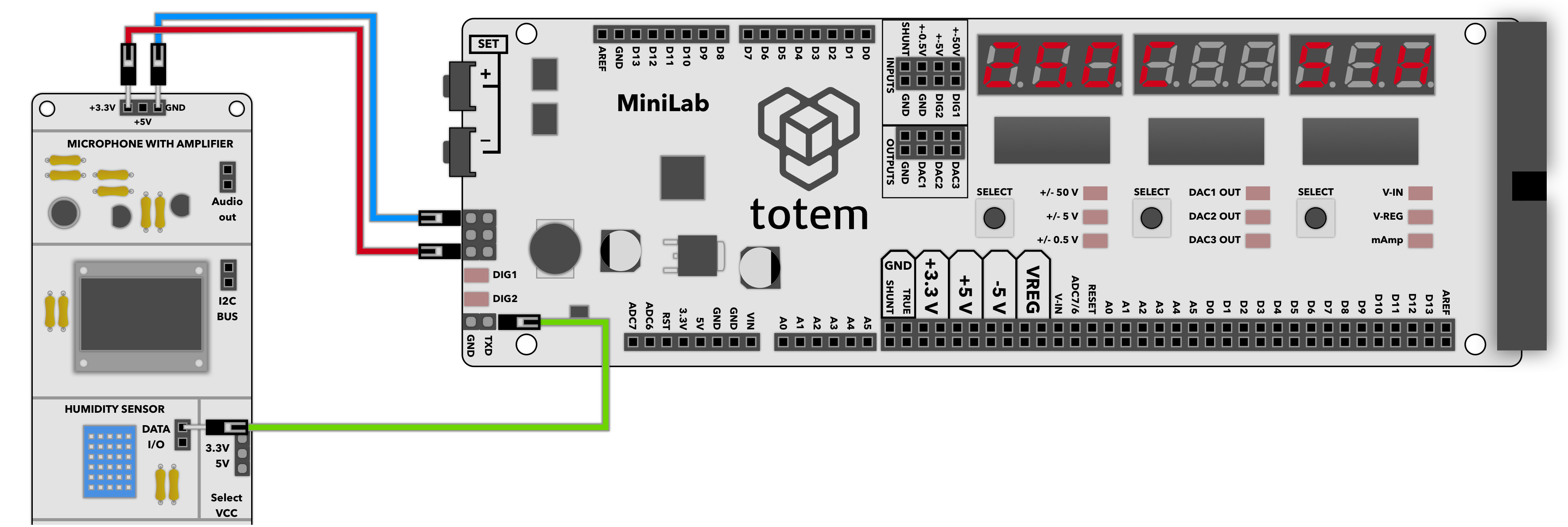 Read measurements using LabBoard. |
NTC thermistor
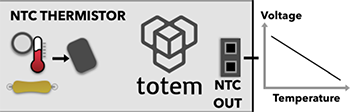
Analog temperature sensor.
Pin header:
- pin 1, 2 - thermistor signal output
Info:
- Arduino example: NTC temperature read.
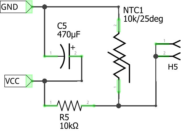
- Negative temperature coefficient (NTC) thermistor working in voltage divider configuration. OUT voltages goes down if temperature increases.
- At room temperature (25 °C) has 10k resistance.
Power:
- Uses VCC for reference voltage.
| Schematic | Experiment |
|---|---|
 |
 |
Buzzer
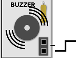
Piezo speaker to produce beeping sounds.
Pin header:
- pin 1, 2 - buzzer enable signal (HIGH - on, LOW - off)
Info:
- Buzzer type: active.
- Can't be used with
tone()function to generate different frequencies. For that case - passive buzzer is required or use Audio side panel.
Power:
- Uses +5v POWER IN to drive buzzer.
| Schematic | Experiment |
|---|---|
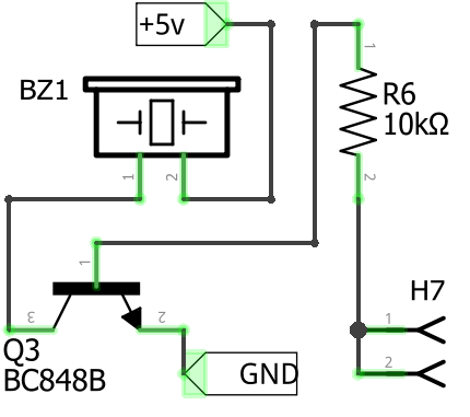 |
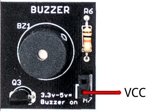 Turn on buzzer by connecting VCC to H7. |
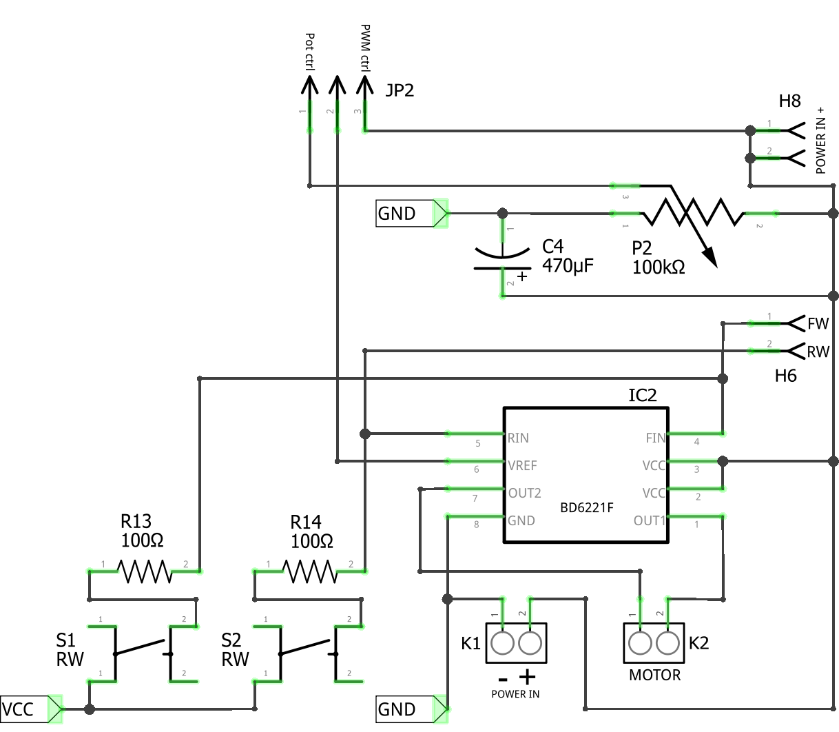
DC motor driver
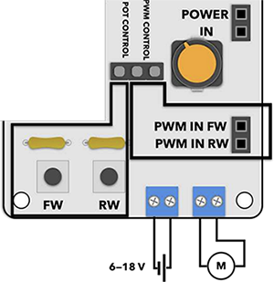
DC motor driver with BD6220F chip.
Supports two speed control types: manual with potentiometer and buttons or modulated signal input.
Control:
- button FW - manual spin motor forward.
- button RW - manual spin motor reverse.
- potentiometer - manual motor speed control.
- JP2: POT CONTROL - use potentiometer control.
- JP2: PWM CONTROL - use PWM pin control.
Pin header:
- PWM IN FW - PWM motor speed control (forward direction)
- PWM IN RW - PWM motor speed control (reverse direction)
- POWER IN 1, 2 - supply power for motor (18V max)
- K1 power in - supply power for motor (screw terminal)
- K2 motor output - motor output pins (screw terminal)
Info:
- Arduino example: Speed and direction control.
Manual control mode:
Place JP2 to POT CONTROL. In this mode motor speed and direction can be controlled using buttons and potentiometer.
Wire motor to screw terminals. Supply power for motor trough POWER IN (or screw terminal).
Click FW button to spin motor forward direction.
Click RW button to spin motor reverse direction.
Turn potentiometer to control motor speed.
Signal control mode:
Place JP2 to PWM CONTROL. In this mode motor speed and direction is controlled using PWM IN input pins. Potentiometer won't work.
Wire motor to screw terminals. Supply power for motor trough POWER IN (or screw terminal).
Supply PWM signal to PWM IN FW pin to spin motor forward. Control speed with duty cycle.
Supply PWM signal to PWM IN RW pin to spin motor reverse. Control speed with duty cycle.
May use LabBoard Pulse generator mode to supply control signal. Wire TXD (typically set 100Hz and adjust duty cycle to change speed).
Motor state depending on input signal:
| Input FW | Input RW | Motor state |
|---|---|---|
| LOW | LOW | Idle |
| HIGH (PWM) | LOW | Rotation FW |
| LOW | HIGH (PWM) | Rotation RW |
| HIGH | HIGH | Brake |
Power:
- All required power has to be supplied trough POWER IN 1, 2 pins or K1 power in. It does not use main power input (top of side panel).
- POWER IN pin is used to power motor from LabBoard (e.g. connecting to VIN pin). K1 power in screw terminal is used to power motor from external battery or power supply by connecting - and +.
| Schematic | Experiment |
|---|---|
 |
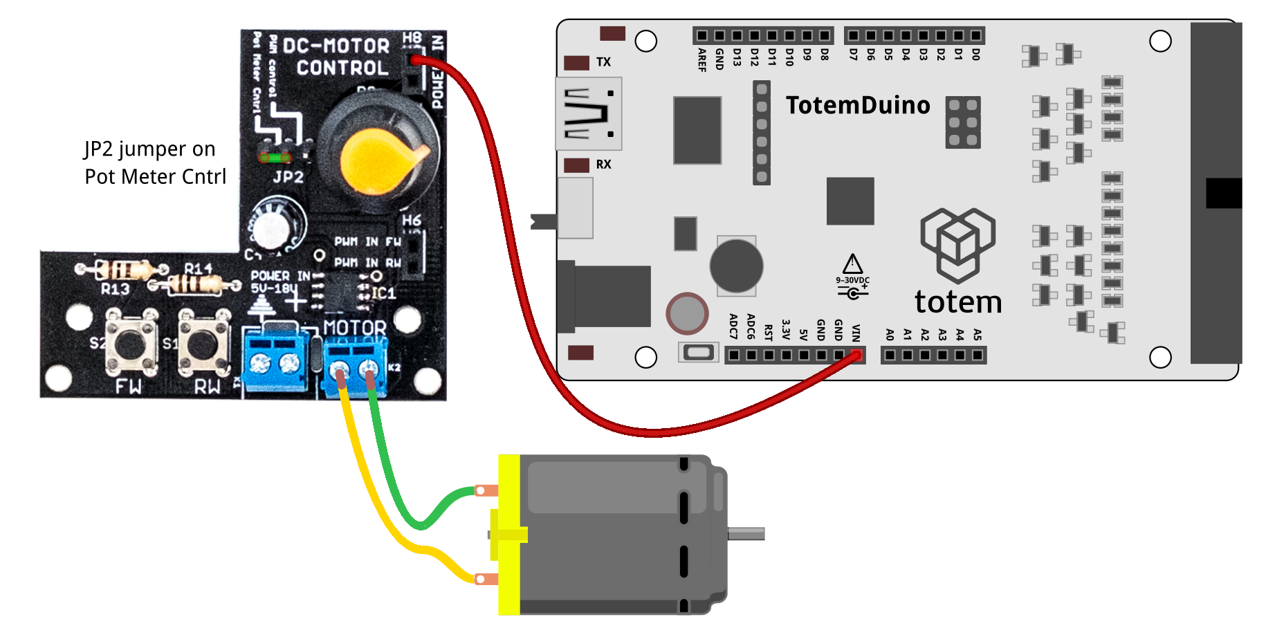 Press FW of RW button to spin motor. Turn potentiometer to control speed. |
Legacy documentation of #2 Sensor side panel:
This page contains latest documentation of audio side panel. Link below is outdated and only specified for reference.
Version 1.1 datasheet (legacy)