Getting started
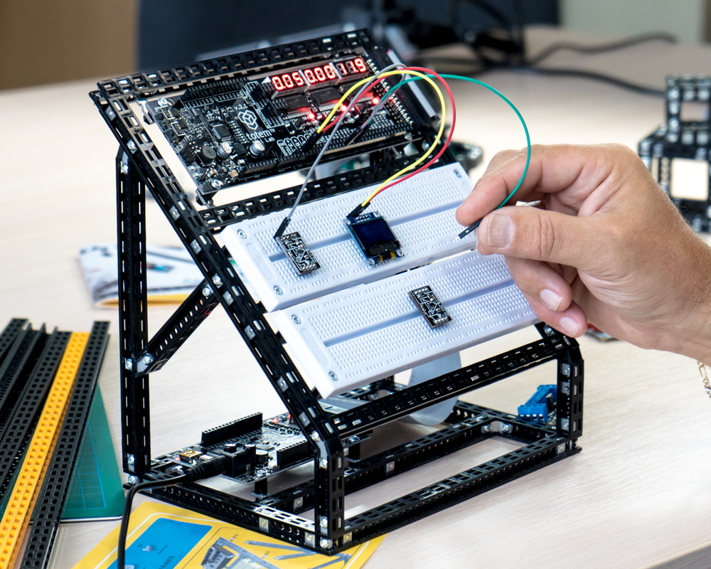
The kit provides easy way to connect components, use LabBoard for measurements and TotemDuino for programming. Additional side panels contains many useful components, conveniently accessible on a single board.
Assembly guide can be found in Mini Lab section.
Power up
Mini Lab can be powered with supplied DC adapter or trough USB. These inputs are located in TotemDuino board. It is suggested to use DC adapter for all available features to work. Both cables can be plugged also (e.g. to power up and program TotemDuino from PC). For more information about power distribution read Power scheme section.
Layout
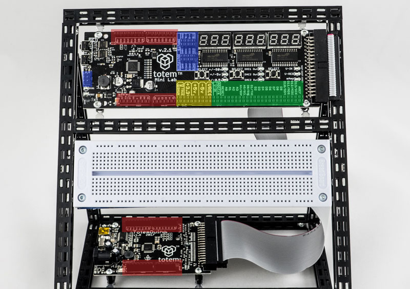
LabBoard is a main central area that provides power, measurement features and extends TotemDuino to make all the pins easy accessible. There are a lot of pin headers, each one with different functionality. Check image and description below for more information. To control LabBoard and its features read LabBoard features section.
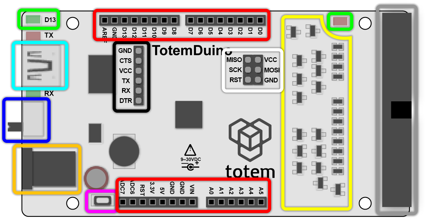
- Red area - TotemDuino pins mirrored to LabBoard over flat cable. Both are Arduino UNO form factor (shields compatible), has same markings and can be used interchangeably. Top ones are easier to reach.
- Green area - TotemDuino pins (red ones) mirrored to additional pin header for easier layout.
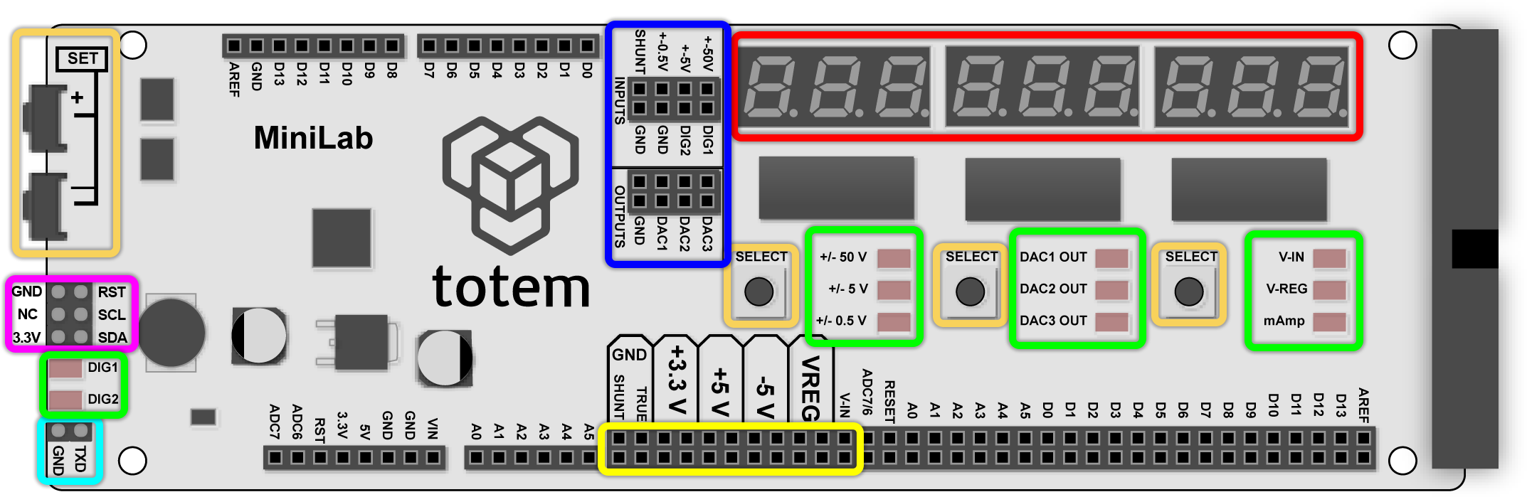
- Blue area - LabBoard specific pins (separated from TotemDuino) for measurements and other features.
- Yellow area - Pins for regulated power output. Read power scheme section for more information on how power rails are distributed across Mini Lab.
| TotemDuino detail layout | LabBoard detail layout |
|---|---|
 |
 |
Breadboard
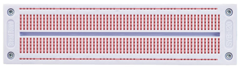
Breadboards are used to make circuit prototypes or to connect components together. They can be snapped in to the grid of holes with contacts underneath. This allows to make circuitry using jumper cables, without require to solder. Holes are connected together in a certain way (see picture above).
Breadboard has numbers and letters to identify hole location. Make sure to mount ir correct way up.
- ━ Horizontal lines - mainly used to distribute power (3V,5V,GND) as it covers whole length of the board.
- ┃ Vertical lines - mainly used to place components. Lines can be connected together using jumper wires.
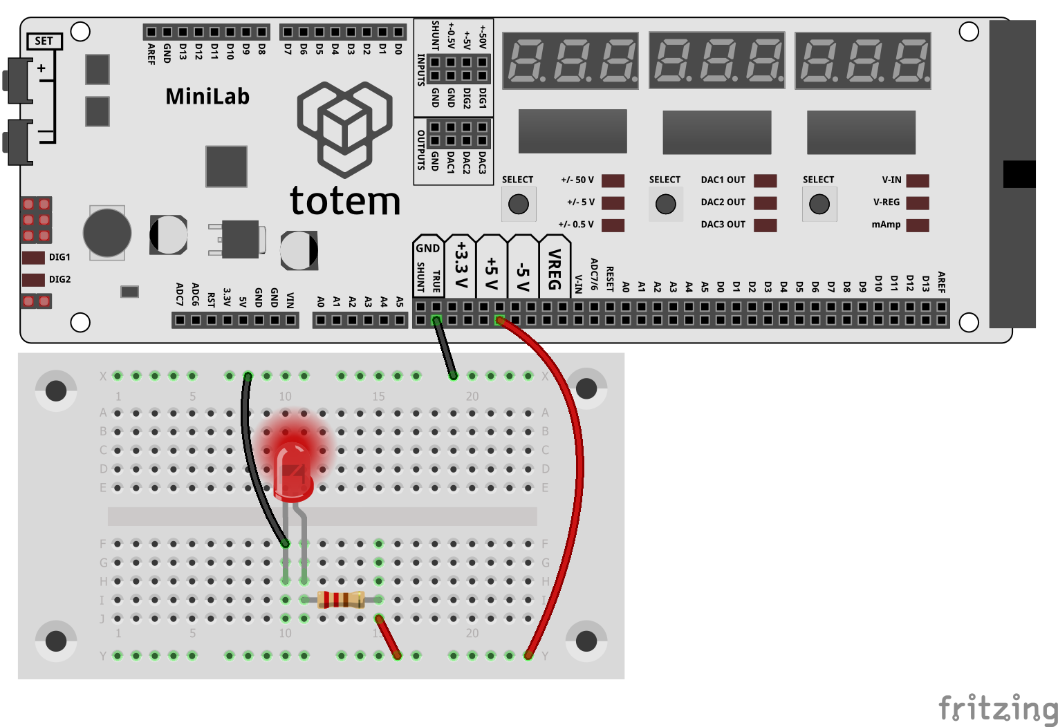
Example of using breadboard:
Programming
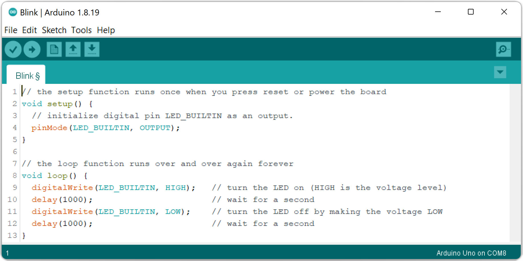
TotemDuino is a programmable development board and can be used to control components during experiments with Mini Lab. It is fully backwards compatible with Arduino UNO platform, so Arduino IDE can be used to upload firmware for TotemDuino as well.
Using mini USB cable you can transfer new firmware sketches into TotemDuino. While you can use different programming environments to write firmware for it, using Arduino is one of the most friendliest and quickest way to start.
Setup Arduino
To write code for TotemDuino board, an Arduino IDE application is required. Follow Setup instructions.
Setup Arduino
Understand Arduino
Arduino code is based on C++ programming language. Also there is an additional set of functions to control pins and other features.
Arduino language reference
Learn Arduino
TotemDuino is used to attach and control various components like LED, buttons, potentiometers and much more. To learn about basic components read Arduino lessons.
Arduino lessons
Use side panels with Arduino
Totem Side panels nicely packs standard components that are fundamental to learn electronics. To see how to use them with TotemDuino - see example projects.
Side panel example projects