Overview
Check firmware version
Documentation is written for the latest firmware version. Read Firmware update section to perform this procedure.
TE-PR-1
This board has a dual use - firstly it can be used as an expansion board to the TotemDuino system, offering easily accessible input and output connections, and secondly
- it is a measuring and testing unit, containing multiple features.
LabBoard is designed to be mounted onto Totem beams and boards, as well as to the third part surfaces, with a help of a few bolts and brackets.
Features
- Digital to Analog converter - converter outputting a pre-set voltage:
- 3 channels in the 0..3.25 Volt range (DAC1, DAC2, DAC3)
- 1 channel in the 3..14 Volt range (VREG)
- Voltage measure - three inputs in the ±0.5V, ±5V and ±50V range.
- Current measure - sensing current up to 800 mA.
- Frequency meter - digital signal frequency measurement module for signals up to 23 MHz.
- Pulse counter - digital signal pulse counter, counting up to 999999999 pulses.
- Pulse generator - unit capable of generating finite or infinite series of pulses, with programmable pulse width and period.
- Serial monitor - View serial data output from Arduino and control LabBoard itself.
- I2C scanner - detect HEX address of connected I2C device.
- DHT11 monitor - display connected DHT11 sensor measurements.
- AD9833 control - control connected AD9833 chip parameters.
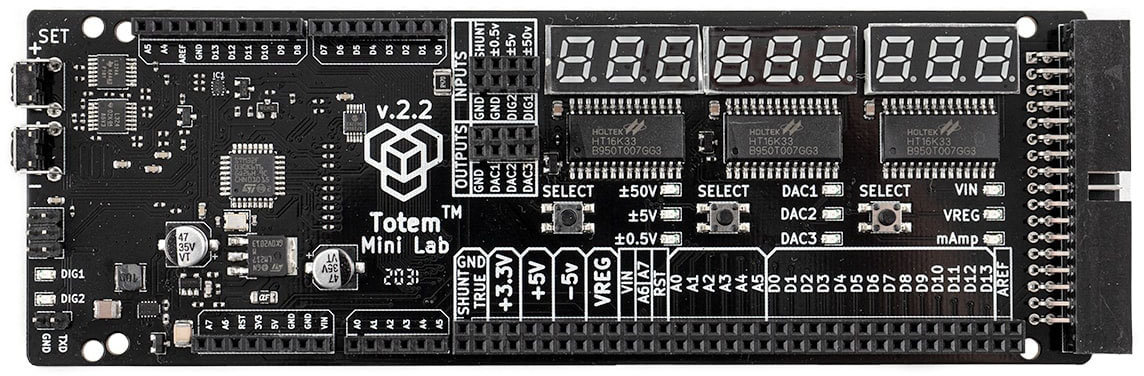
Layout
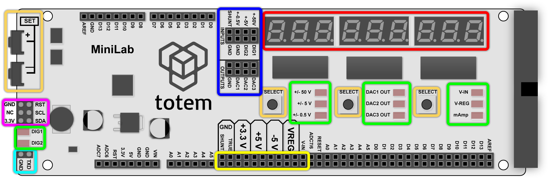
LabBoard works on its own as a separate device, providing additional functionality and convenience of prototyping. Unmarked headers mirrors TotemDuino pins over connected flat cable and are not used in LabBoard functionality (directly).
Description of board items:
- Control keys - SET+ SET- used to increment, decrement values and jump between selections. Left SELECT Middle SELECT Right SELECT used to select certain options, depending on mode LabBoard is running.
- Display - 7-segment display with 9 digits and individual dots. Displays all information related to currently running mode.
- LED - contains total of 11 LED. Groups of 3 (near buttons) are used to indicate currently selected parameter in Main screen mode. DIG1 and DIG2 mostly used to show digital state of DIG1 and DIG2 pins.
- Input / Output - Header for voltage measure and regulated output. There are 3 channels for voltage measurement, 3 channels (DAC) for variable voltage output and 2 digital pins for various functionality.
- SWD header - initially designed to flash firmware, but repurposed to reuse SCL and SDA pins for additional LabBoard functionality (I2C scanner and AD9833 control).
- Power out - provides power for breadboard and other circuits. Outputs regulated voltage of: 3.3V, 5V, -5V, VIN - DC input and VREG - variable between 3V and 14V.
- TXD pin - used to generate configurable output signal in Pulse generator mode. Also used in DHT11 monitor mode.