2. Frequency meter
About
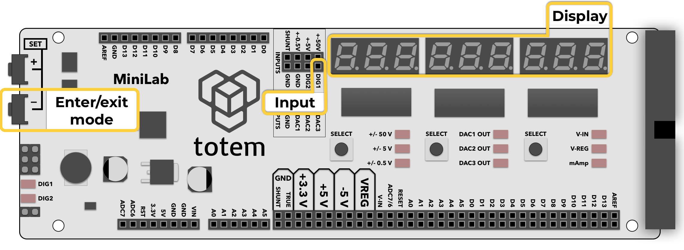
Mode used for measuring signal frequency. Display shows current reading in Hertz or Megahertz units.
Details
- Measure signal frequency at DIG1 pin.
- Maximum frequency up to 23 MHz*.
- Input pin is pulled HIGH (default state).
- Display is updated each second.
- Display will show value in Hertz. If number exceeds 1Mhz - it will switch to Mhz mode.
- Signal HIGH level should be in the amplitude from 2 V to 5 V.
- Left corner LED DIG1 will blink according to input frequency.
It is not directly tied to input pin. Only for visual representation.
* Frequencies larger than 10MHz can be affected by electrical conditions (contacts, wire length, no shielding, etc.). Make sure wires are short and signal is stable enough.
Controls
Enter mode:
- Select Menu >
2. FREq. - (deprecated) In Main screen hold SET- for 3 seconds.
Exit mode:
- Open menu and select other mode.
- (deprecated) Press SET- to exit to Main screen.
Example
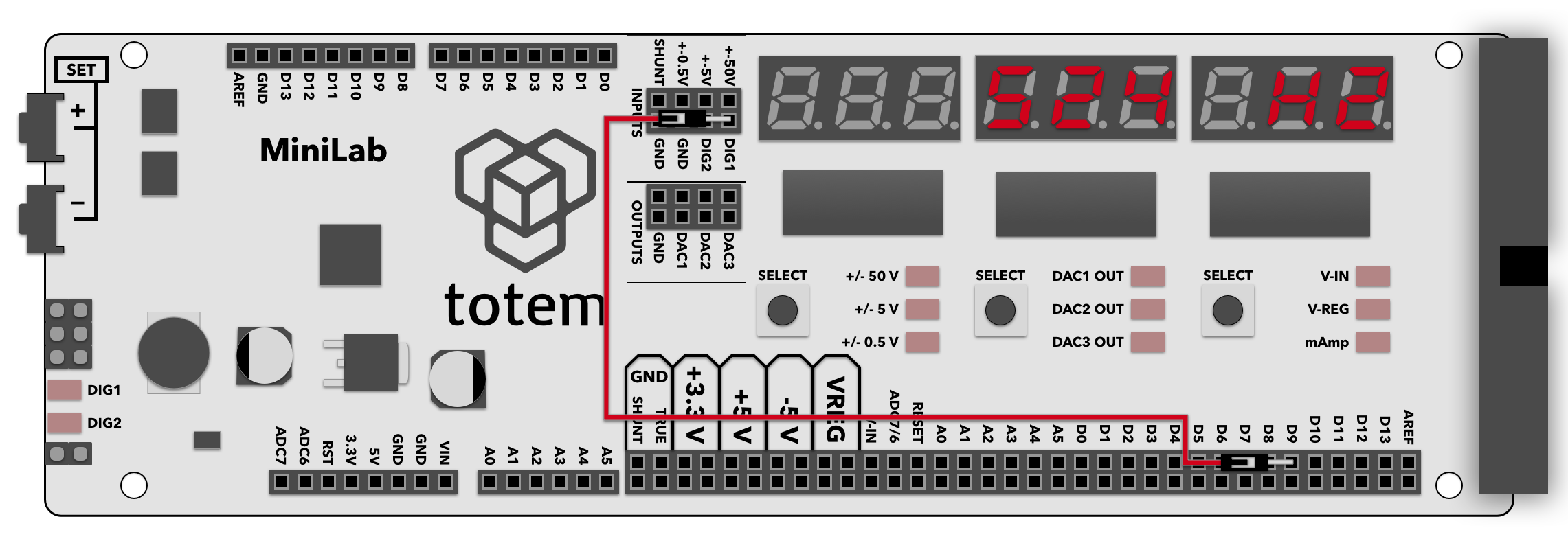
- Connect D9 digital pin to DIG1 frequency meter input.
- Enter frequency meter mode by selecting Menu >
2. FREq. - Load code sketch to TotemDuino. This will output 1kHz frequency on pin D9.
LabBoard should display1000 HZ. Uses tone() function.void setup() { pinMode(9, OUTPUT); // Set pin D9 to output tone(9, 1000); // Output 1kHz frequency to pin D9 } void loop() { } - Load code sketch to TotemDuino. This will output 8Mhz frequency on pin D9.
LabBoard should display8.00000mHZ. Letter 'm' displayed as 2 segments.This code snippet directly writes ATmega328P registers to configure timer 1 to output 8Mhz frequency on pin PB1 (D9).void setup() { // Set pin D9 to output DDRB |= (1 << PB1); // Set timer TOP and compare values ICR1 = 1; // TOP OCR1A = 0; // compare (duty cycle) // Set no prescaler, Fast PWM mode (14) TCCR1A = (1 << COM1A1) | (1 << WGM11) ; TCCR1B = (1 << CS10) | (1 << WGM12) | (1 << WGM13); } void loop() { }