Main screen
About
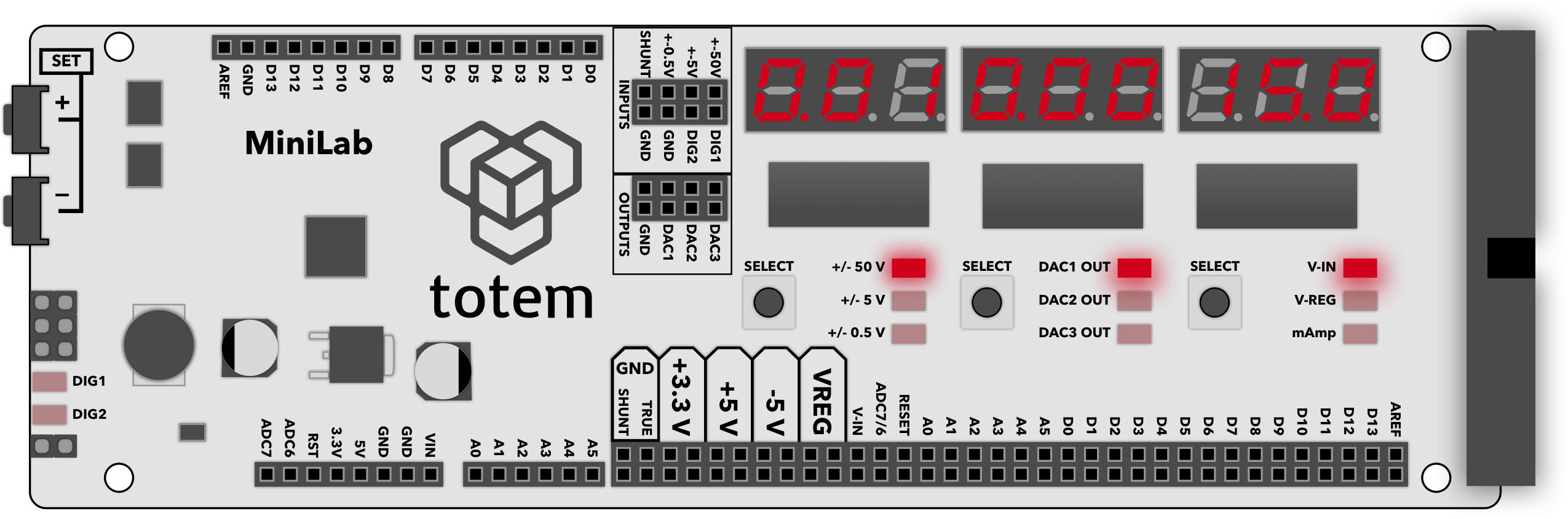
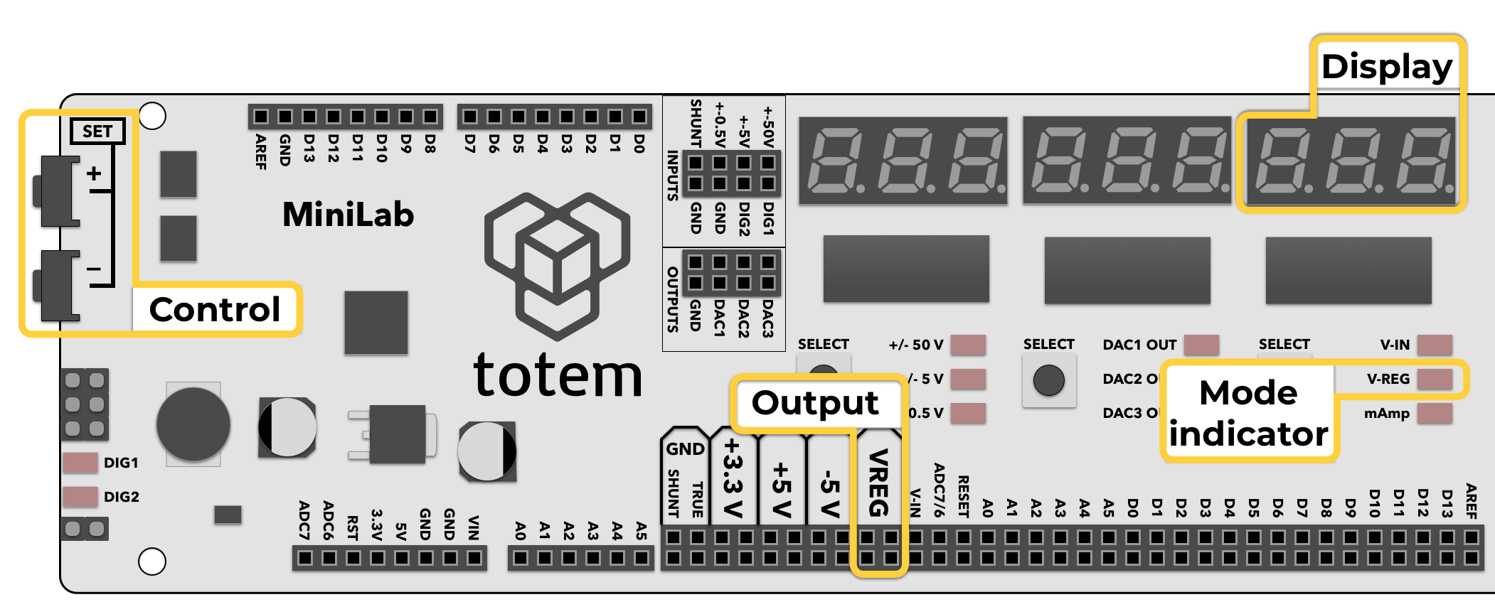
Main "home" screen of LabBoard contains most of its functionality. Display and buttons are divided into 3 separate features working in parallel.
Details
- Voltage measure of selected input: ±0.5V, ±5V, ±50V
- 3 channels of variable voltage DAC outputs 0..3.25V
- 1 channel of variable voltage VREG output 3..14V
- DC input voltage (VIN) display
- Current measure up to 800 mAmps
- 2 LED to display DIG1 and DIG2 pin state (HIGH, LOW)
Left display
Voltage measurement
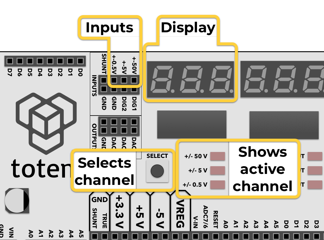
LabBoard has a 3 channel voltage measurement module. Each has a pre-set measurement range:
- ± 0.5 V - for measuring small scale signals when maximum precision is required.
- ± 5 V - for measuring TTL logic level signals.
- ± 50 V - for external signal measuring.
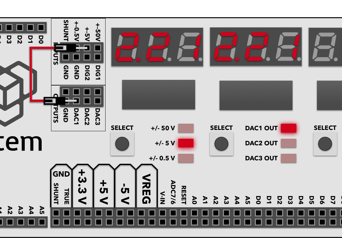
Left display is used in the LabBoard for showing currently measured voltage. Active channel can be selected with a Left SELECT button under the display. Corresponding channel LED will light up.
Display shows value in millivolts when using ± 0.5 V channel, otherwise the output is in Volts.
--- is displayed if measured voltage is out of range.
Blinking display indicates that currently measured voltage is negative.
If measurements are incorrect - perform Calibration or fine tune with ADC manual offset.
Example:
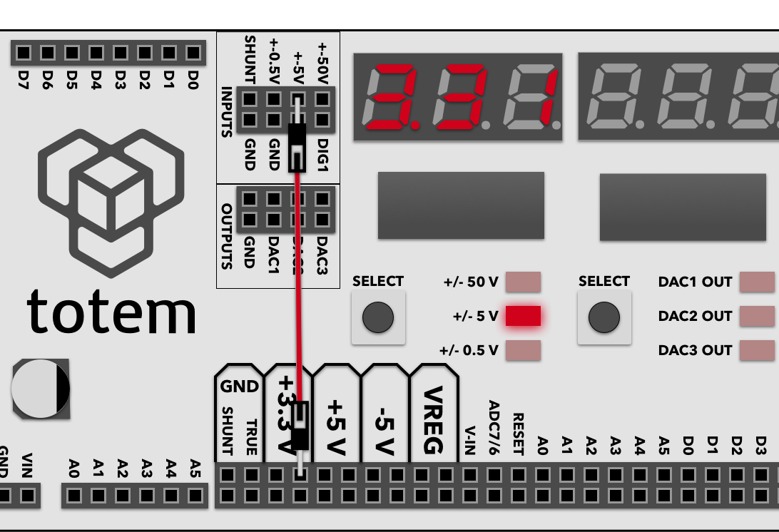
- Connect the ± 5V input with a +3.3 V output.
- Press Left SELECT button until the ±5V input LED lights up.
- Observe the display - it should indicate a value close to 3.3 Volts:
Middle display
DAC output
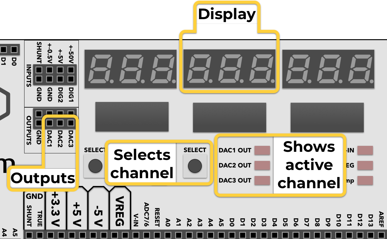
Inbuilt 3 channel Digital to Analog Converter (DAC) allows you to output any voltage in the 0..3.25 Volt range, at up to 15 mA current. This is useful for experimenting with comparators or operational amplifiers, as they need various reference or input voltages.
Middle display shows current output voltage for the active channel, which itself is indicated by the middle column of LED’s. To change DAC output voltage:
- Press Middle SELECT to select active channel.
- Hold Middle SELECT until LED starts to blink.
- Use SET+ and SET- buttons to adjust currently selected channel voltage.
Hold button down for fast increment. It will stop at 0 and 3.25. - Press Middle SELECT to exit edit mode.
All other inactive channels will still keep the same preset voltage until it’s changed by SET buttons on the side of the board.
Example:
- Connect the DAC1 output to the ± 5 V voltage measuring channel input.
- Using Left SELECT button switch the measure channel to ± 5 volts.
- Using Middle SELECT button switch the current output channel to DAC1 Out.
- Hold Middle SELECT button until DAC1 Out LED starts to blink.
- Using SET+ and SET- buttons change the output value of the DAC1 channel.
- Observe that voltage measure display follows the same value as the DAC output one.
Right display
VIN measurement
When VIN mode is selected - it displays current voltage of VIN pin. It depends on DC power adapter. Typically it is 15 Volts. Older kits had 12 V power adapter.
--- is displayed if DC jack is not connected and VIN is not available.
This mode is only for observation and does not contain any more features.
VREG output
LabBoard has a built-in variable voltage output module, capable of providing up to VIN - 1V at up to 500 mA. VIN is the supply voltage for the Mini Lab. Typically output voltage can be adjusted between 3 and 14 Volts.
The selected voltage is shown on the right display when VREG mode is activated. To change output voltage:
- Press Right SELECT to select VREG mode.
- Hold Right SELECT until LED starts to blink.
- Use SET+ and SET- buttons to adjust output voltage.
Hold button down for fast increment. - Press Right SELECT to exit edit mode.
not is displayed if feature is not available, because DC jack is not connected or below minimum voltage.
Example:
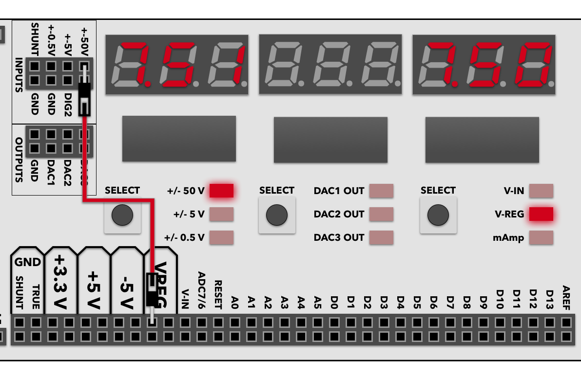
- Connect VREG together with ± 50V input.
- Set the VREG voltage to some value.
- Observe that the ± 50V input measurement follows the VREG setting.
Current measurement
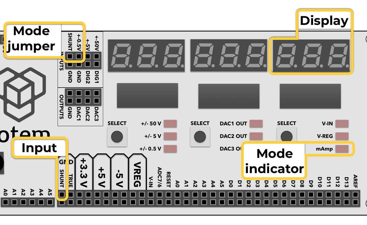
LabBoard has a current measurement module for up to 800 mAmps. Rightmost display is used for showing current measurement result, when the mAmp mode is selected. As the current sensor reuses the same hardware as used in voltage measurement module - you need to connect the signal from the shunt resistor with ± 0.5V channel.
Example:
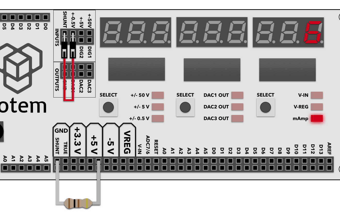
- Connect SHUNT and ± 0.5V input together.
- Connect any external circuit (in this example a 100 Ohm resistor is used), powering it from the LabBoard +5V output, but instead of connecting negative end to ground, connect it to SHUNT GND pin.
- Using Right SELECT button switch into mAmp mode.
- Observe that it measures close to 5 mA.
Digital input
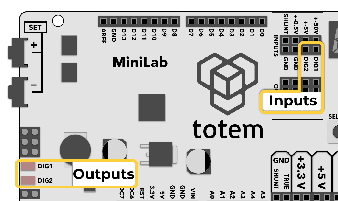
LabBoard has a two channel digital input module, meant to indicate the current logic state of the DIG1 and DIG2 pins with an LED. Default (unconnected) logic level is LOW.
0 to 6 Volts are accepted input range. A low input value (0..1.3V) turns off corresponding LED, where a high value (1.8..6V) turns the LED on.
Example:
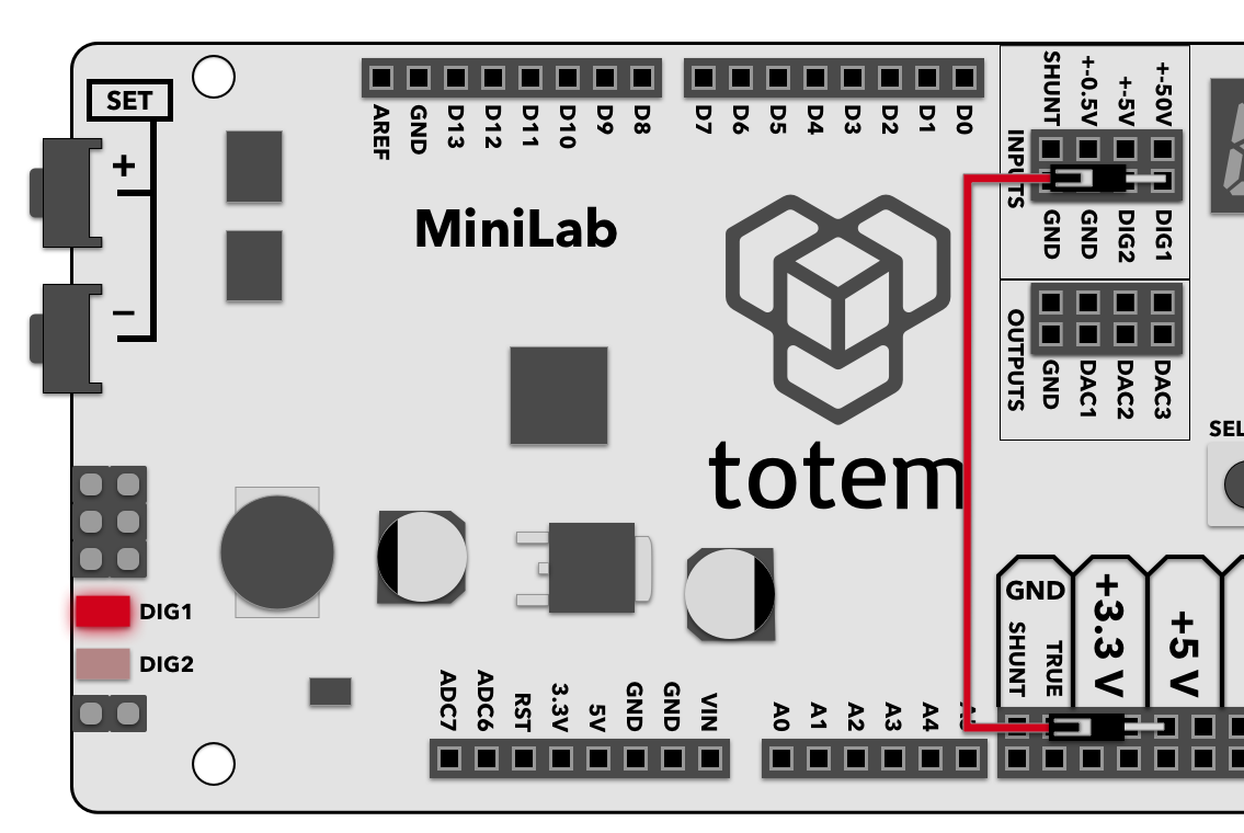
- Connect DIG1 input with +5V output
- Observe that DIG1 LED follows the state of the input by lighting up.