1. Pulse counter
About
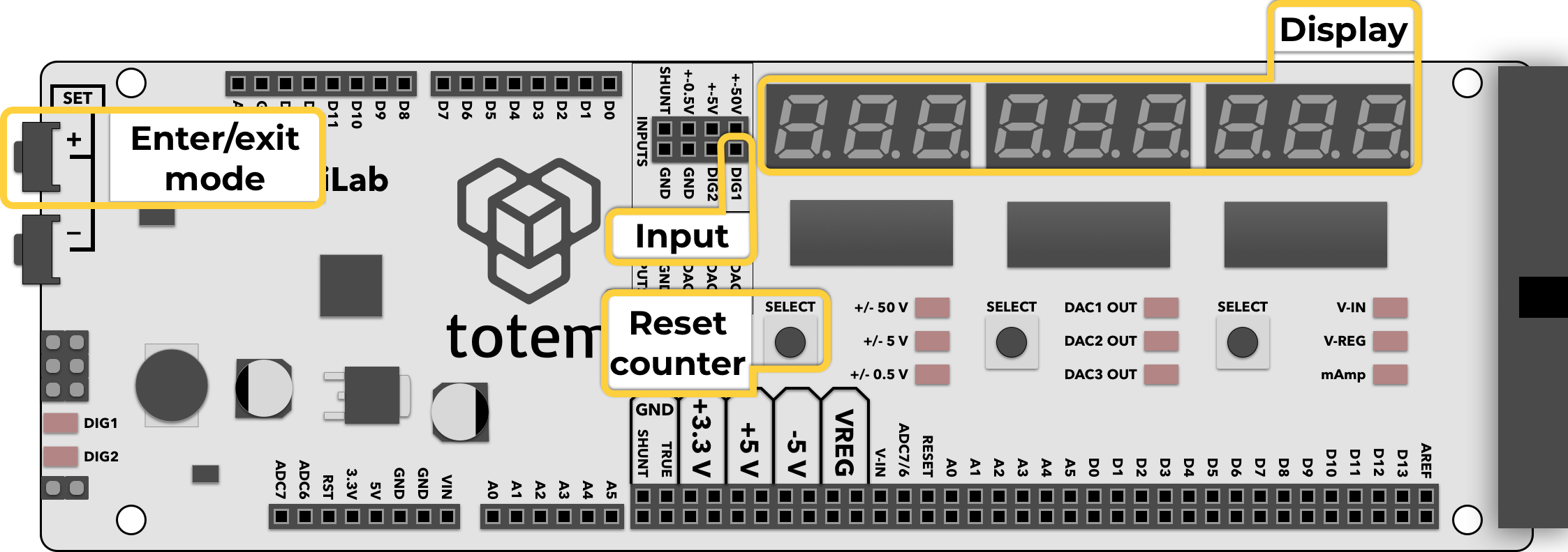
Mode used for counting number of pulses in a signal. Display shows total number of pulses and increments with each new one. Count value can be reset any time with a button press.
Details
- Count signal pulses at DIG1 pin.
- Maximum frequency up to 23 MHz*.
- Input pin is pulled HIGH (default state).
- Display is updated each pulse. Value will overflow after 999999999.
- Signal HIGH level should be in the amplitude from 2 V to 5 V.
- Left corner LED DIG1 will light up according to signal state (HIGH or LOW).
It is not directly tied to input pin. Only for visual representation.
* Frequencies over 10MHz can be affected by electrical conditions (contacts, wire length, voltage, no shielding, etc.). Make sure wires are short and signal is stable enough.
Controls
Reset counter to 0:
- Click Left SELECT
Switch between detection edge (does not change pull-up):
- Click Right SELECT to change mode:
On HI- count on rising edge ⎽/⎺ (default)On LO- count on falling edge ⎺\⎽
Enter mode:
- Select Menu >
1. COUNt. - (deprecated) In Main screen hold SET+ for 3 seconds.
Exit mode:
- Open menu and select other mode.
- (deprecated) Press SET+ to exit to Main screen.
Example
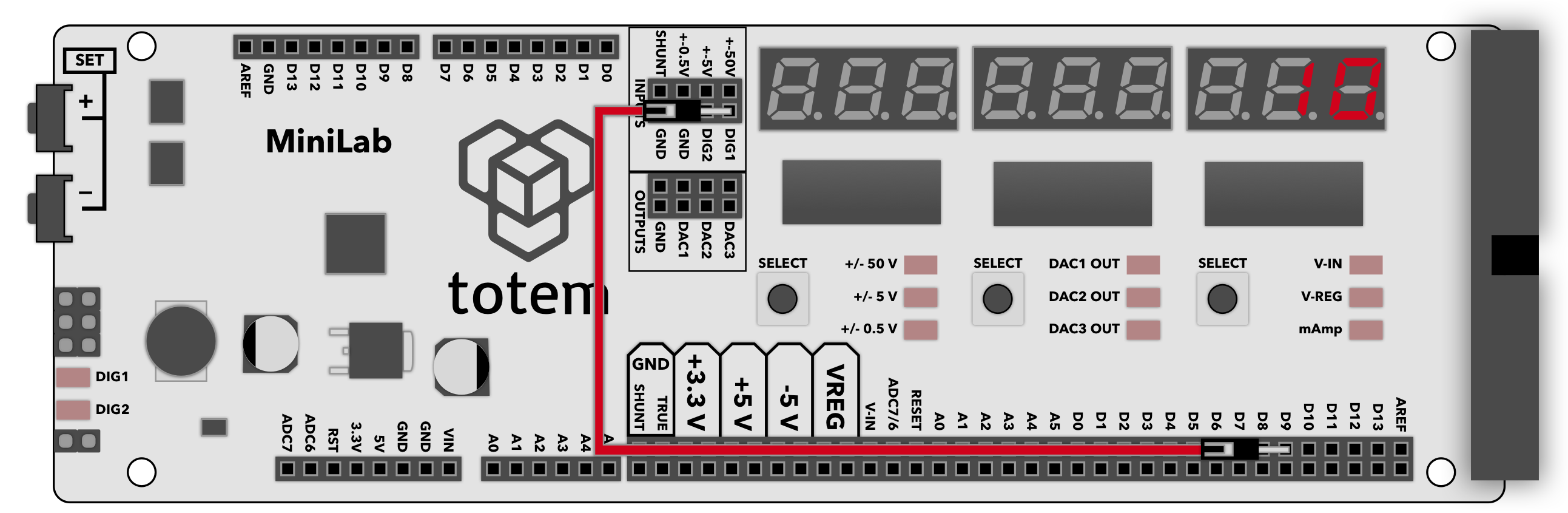
- Connect D9 digital pin to DIG1 pulse counter input.
- Enter pulse counter mode by selecting Menu >
1. COUNt. - Load code sketch to TotemDuino:
void setup() { pinMode(9, OUTPUT); // Set pin D9 to output } void loop() { for (int i=0; i<10; i++) { // Repeat 10 times digitalWrite(9, HIGH); // Set pin D9 HIGH digitalWrite(9, LOW); // Set pin D9 LOW } delay(500); // Wait 500ms } - Observe that the counter increments by 10 every 0.5 second.
- Click Left SELECT to reset counter value.