4. Serial monitor
Select board revision
This tutorial differs between board revisions. Please select the one you have:
v.2.1  |
v.2.2 |
v.2.3  |
 |
| v.2.1 |
v.2.2 |
v.2.3 |
|
Check firmware version
Documentation is written for the latest firmware version. Read Firmware update section to perform this procedure.
Exit serial mode
To exit back to menu from serial mode - press both SET+ SET- keys at the same time (instead of any two keys). This is done to allow freely use of LabBoard keys without interruption.
Serial mode allows to communicate with LabBoard over serial (UART) and control its features. This interaction can read or write values using Serial protocol commands, enabling external LabBoard control from TotemDuino or PC. This can be used for debugging or as integral part of application (view and control). Multiple features are available:
- Read measurements
- Set output voltage
- Control signal generator
- Interact with keys, LED and display
- Print serial on display
Serial.println("Arduino") - Control LabBoard features over Serial protocol
- Control LabBoard features with Totem Library from Arduino
Main settings
There are multiple ways to use serial communication. When enabling serial mode, LabBoard will ask to choose required configuration:
- Baud rate: Communication speed. Must match with one used in
Serial.begin(baudrate)or serial terminal application - Direction: Selection between
PCandArduino. Swaps TX, RX pins depending on endpoint device (the one who sends commands to LabBoard) - Background mode: Enabled in settings ("Always on"). Activates serial in normal LabBoard operation mode to work concurrently
Connect to Arduino
Enables communication with Arduino boards over D0 and D1 pins.
Serial protocol commands can be sent using Serial: Serial.println("LB:OUT:DAC1:500").
Totem Library provides convenient wrapper functions LB.volt.setDAC1(500) to use within Arduino environment. Read Serial API reference for more information.
Arduino examples: Github
Wiring instructions:
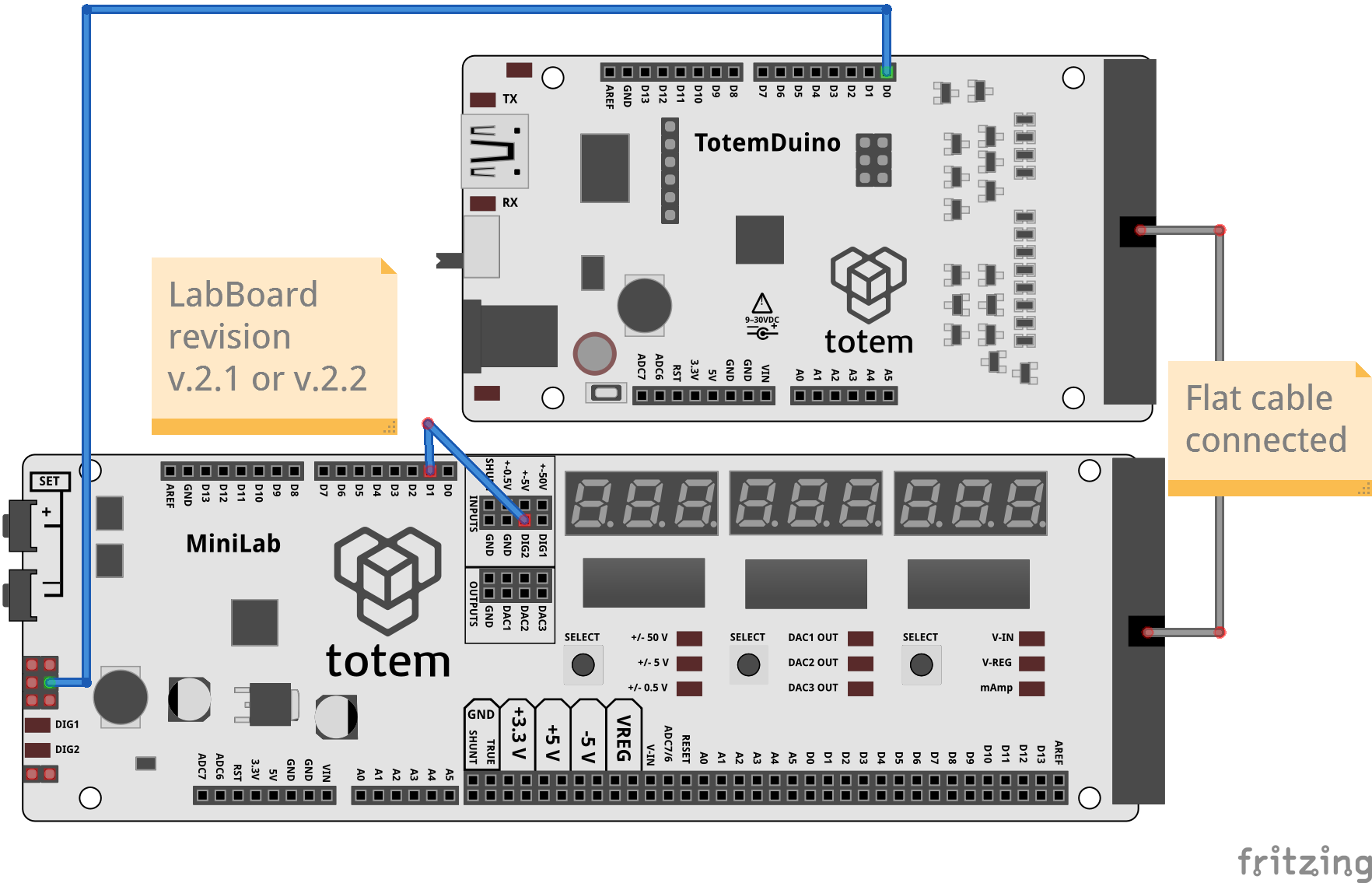
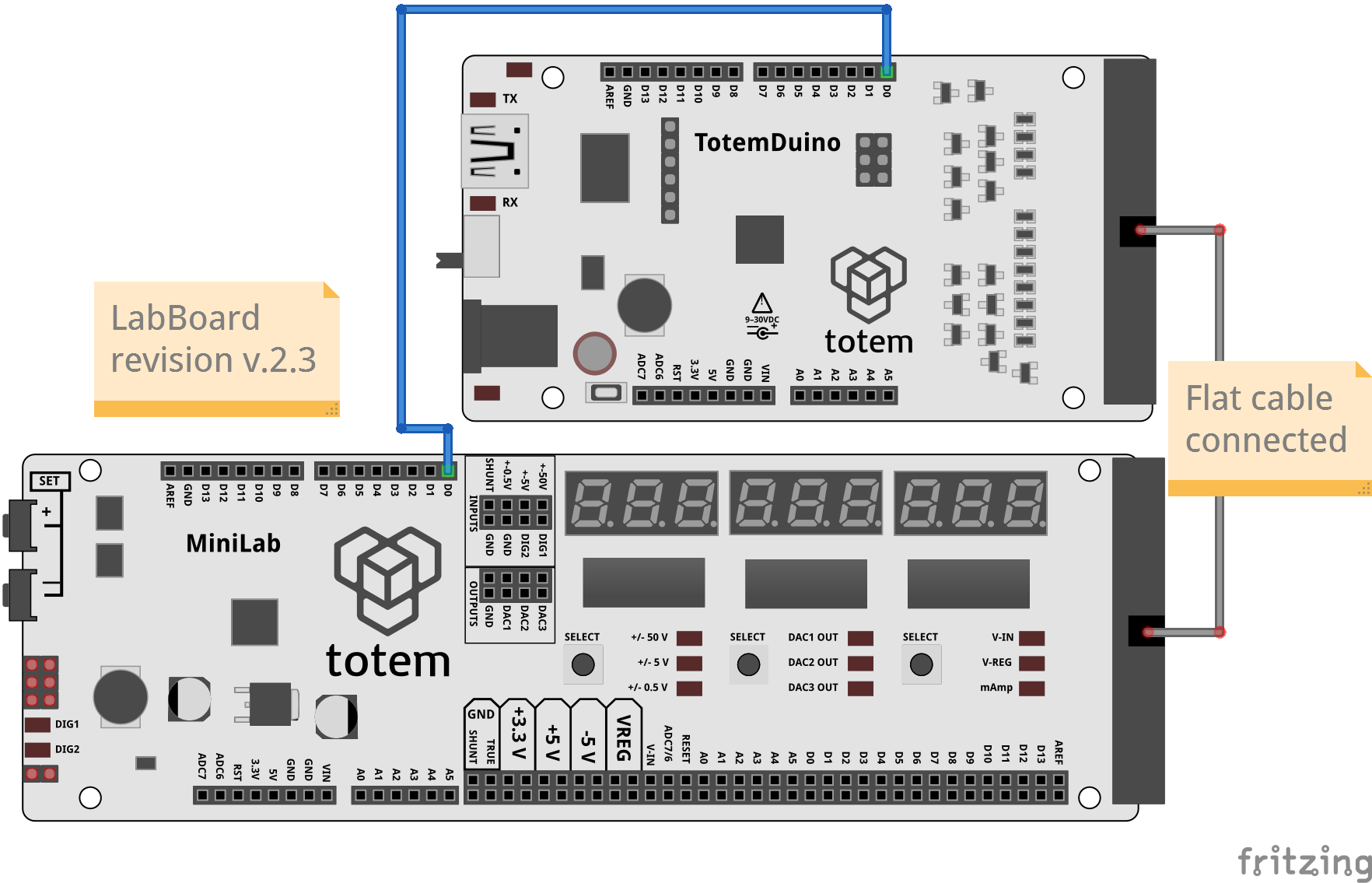
Connect with TotemDuino
Direction: Arduino.
Control: From sketch running on TotemDuino.
Power: From TotemDuino DC jack or USB.
Required wiring:
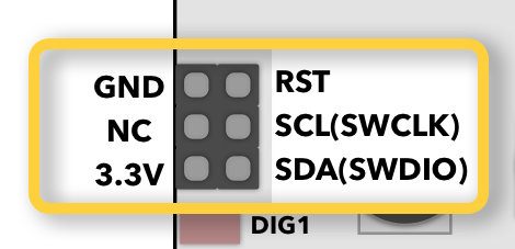
- TotemDuino D0 to LabBoard SCL (SWD header pinout)
- LabBoard D1 to LabBoard DIG2
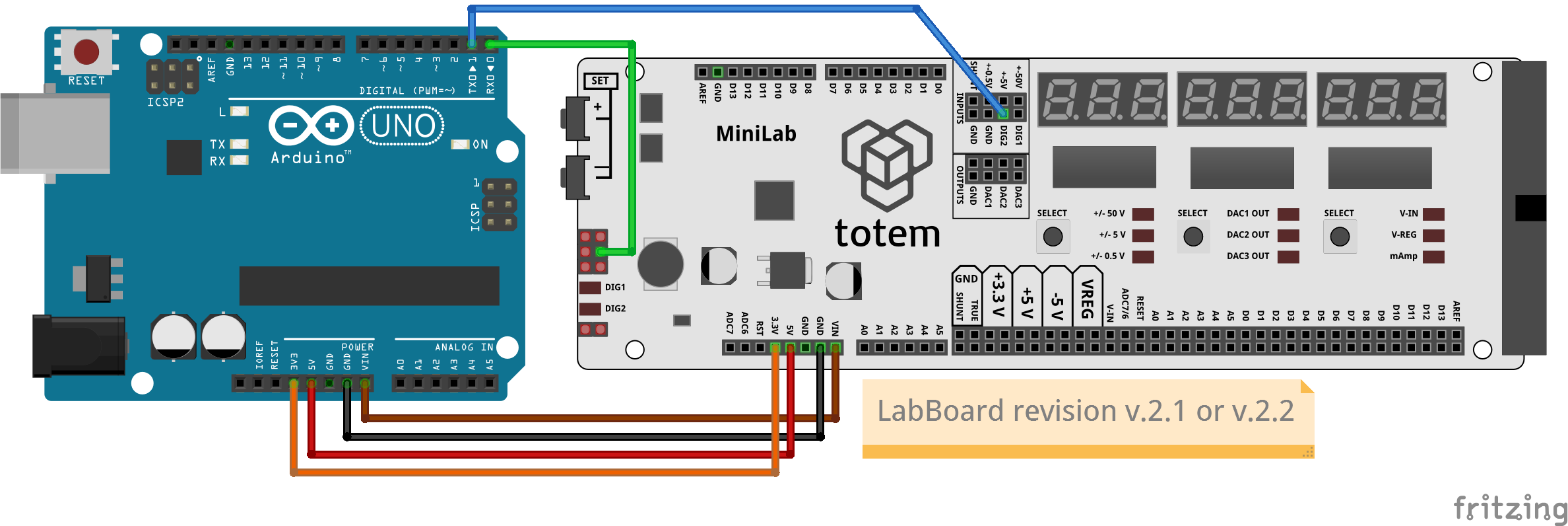
Connect with Arduino boards
Direction: Arduino.
Control: From sketch running on Arduino board.
Power: From Arduino board DC jack or USB.
Flat cable is not connected.
Voltages 3.3V, 5V, VIN are provided by Arduino board. LabBoard does not have voltage regulator (Power scheme).
Required wiring:
- D0 to LabBoard SCL (SWD header pinout)
- D1 to LabBoard DIG2
- 3V3 to LabBoard 3.3V
- 5V to LabBoard 5V
- GND to LabBoard GND
- VIN to LabBoard VIN
Wiring instructions:
Connect with TotemDuino
Direction: Arduino.
Control: From sketch running on TotemDuino.
Power: From TotemDuino DC jack or USB.
Required wiring:
- TotemDuino D0 to LabBoard D0
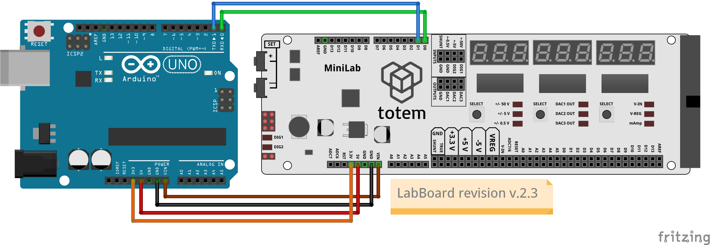
Connect with Arduino boards
Direction: Arduino.
Control: From sketch running on Arduino board.
Power: From Arduino board DC jack or USB.
Flat cable is not connected.
Voltages 3.3V, 5V, VIN are provided by Arduino board. LabBoard does not have voltage regulator (Power scheme).
Required wiring:
- D0 to LabBoard D0
- D1 to LabBoard D1
- 3V3 to LabBoard 3.3V
- 5V to LabBoard 5V
- GND to LabBoard GND
- VIN to LabBoard VIN
- Select serial mode -
4. SERIAL. - Change value with SET+, SET-. Confirm with Right SELECT.
- Select baud rate (speed) -
bAU 57600.
Must match the one set inSerial.begin(57600). - Select direction -
Arduino. - Mode is active and displays
Serial.
Connect to PC
Enables communication with external devices, capable to interpret serial data. This allows to connect data stream to PC over USB or use other device to communicate over TX and RX.
LabBoard control can be achieved using Serial protocol commands.
Python examples: Github
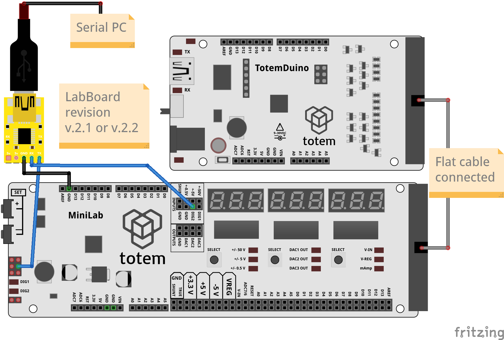
Wiring instructions:
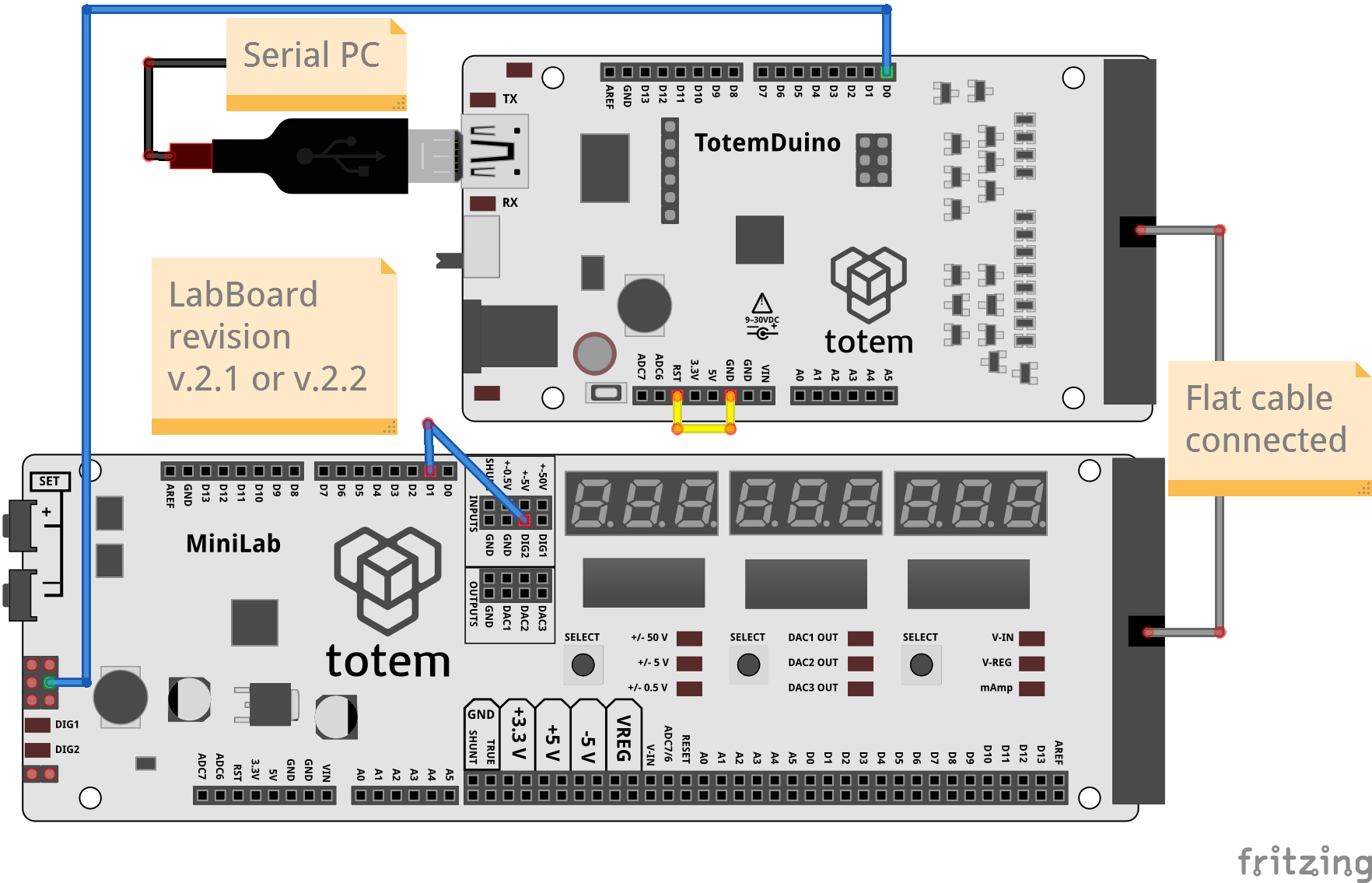
Connect over TotemDuino
Direction: PC.
Control: From PC over TotemDuino as passthrough.
Power: From TotemDuino DC jack or USB.
TotemDuino will be disabled to act as passthrough for direct LabBoard communication with PC.
Required wiring:
- TotemDuino D0 to LabBoard SCL (SWD header pinout)
- LabBoard D1 to LabBoard DIG2
- RST to GND (disable TotemDuino)
Connect over USB-Serial converter with TotemDuino
Direction: PC.
Control: From PC over USB-Serial converter.
Power: From TotemDuino DC jack or USB.
Required wiring:
- TX to LabBoard SCL (SWD header pinout)
- RX to LabBoard DIG2
- GND to LabBoard GND
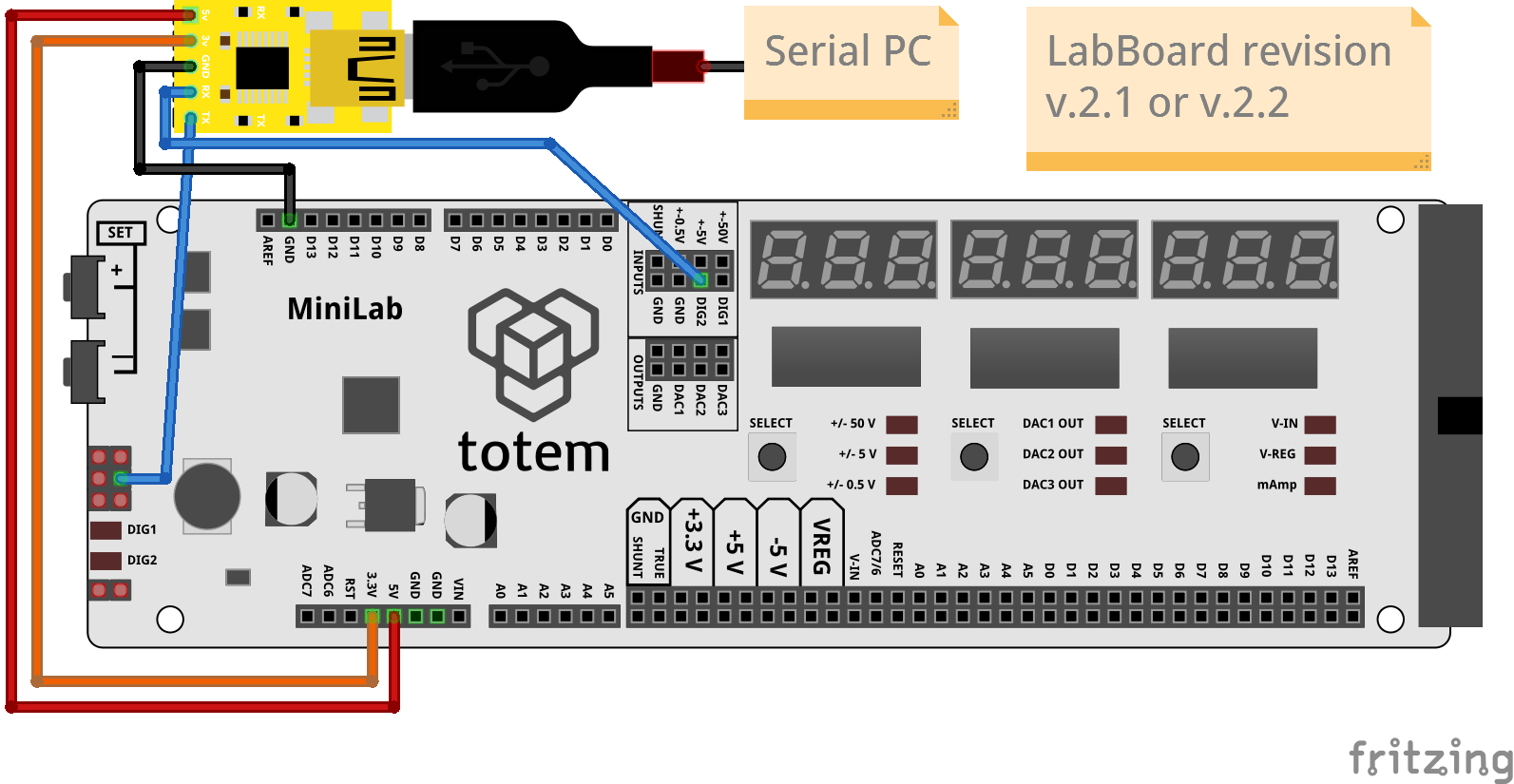
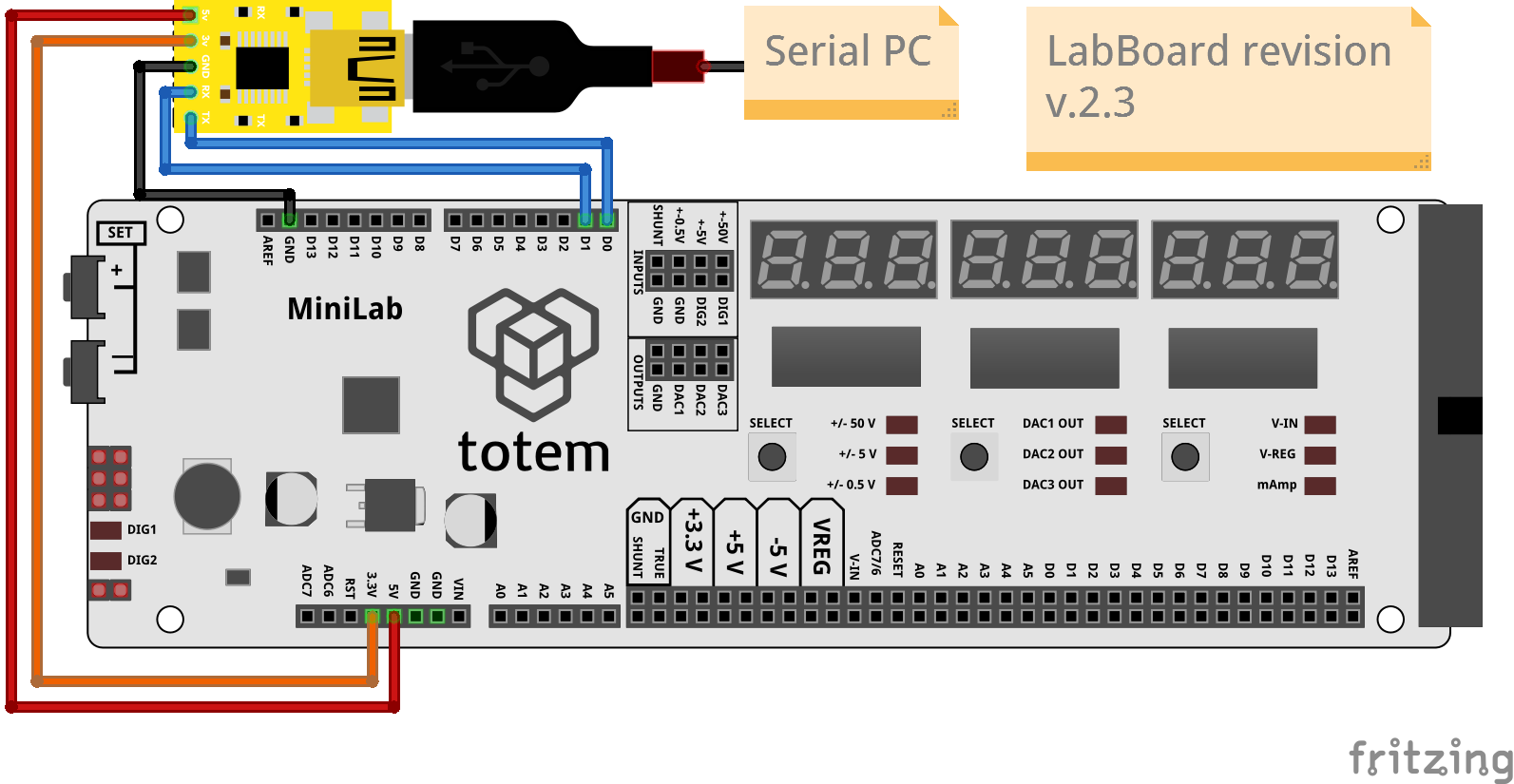
Connect over USB-Serial converter without TotemDuino
Direction: PC.
Control: From PC over USB-Serial converter.
Power: From USB-Serial converter.
Flat cable is not connected.
VIN not available!. Certain LabBoard functionality will not work.
Voltages 3.3V, 5V are provided by USB-Serial converter. LabBoard does not have voltage regulator (Power scheme).
Required wiring:
- TX to LabBoard SCL (SWD header pinout)
- RX to LabBoard DIG2
- GND to LabBoard GND
- 3v to LabBoard 3.3V
- 5v to LabBoard 5V
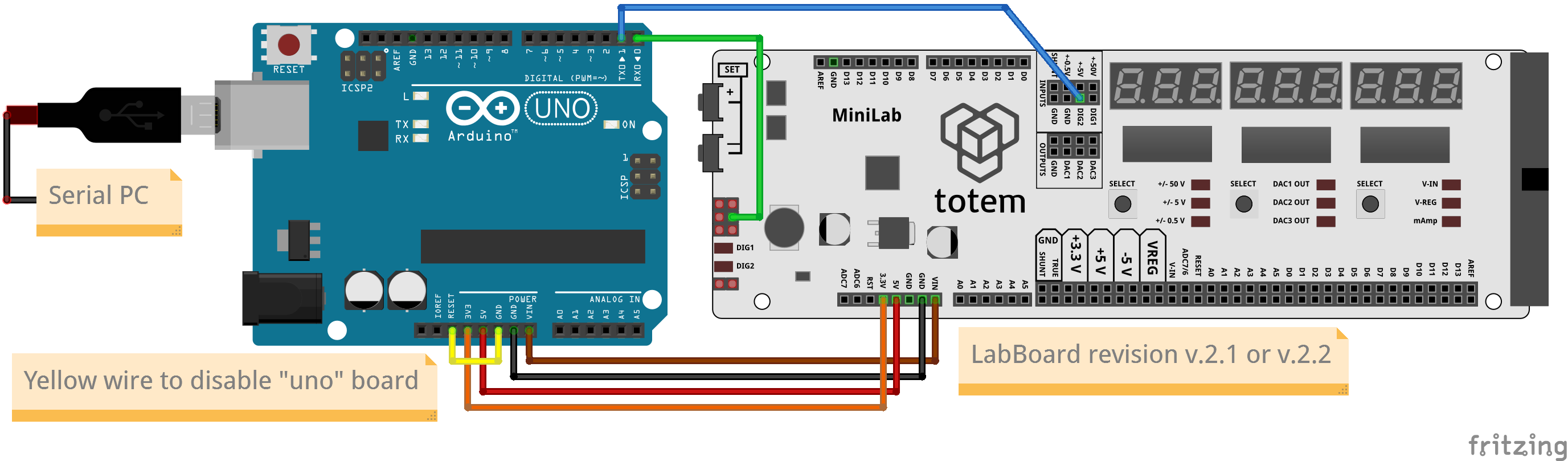
Connect over Arduino board
Direction: PC.
Control: From PC over Arduino board as passthrough.
Power: From Arduino board DC jack or USB.
Flat cable is not connected.
Voltages 3.3V, 5V, VIN are provided by Arduino board. LabBoard does not have voltage regulator (Power scheme).
Arduino board will be disabled to act as passthrough for direct LabBoard communication with PC.
Required wiring:
- D0 to LabBoard SCL (SWD header pinout)
- D1 to LabBoard DIG2
- 3V3 to LabBoard 3.3V
- 5V to LabBoard 5V
- GND to LabBoard GND
- VIN to LabBoard VIN
- RESET to GND (disable Arduino)
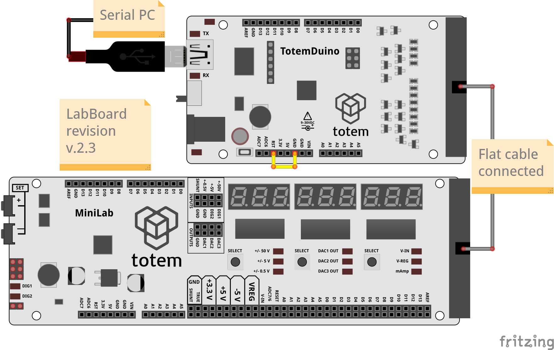
Wiring instructions:
Connect over TotemDuino
Direction: PC.
Control: From PC over TotemDuino as passthrough.
Power: From TotemDuino DC jack or USB.
TotemDuino will be disabled to act as passthrough for direct LabBoard communication with PC.
Required wiring:
- RST to GND (disable TotemDuino)
Connect over USB-Serial converter
Direction: PC.
Control: From PC over USB-Serial converter.
Power: From USB-Serial converter.
Flat cable is not connected.
VIN not available!. Certain LabBoard functionality will not work.
Voltages 3.3V, 5V are provided by USB-Serial converter. LabBoard does not have voltage regulator (Power scheme).
Required wiring:
- TX to LabBoard D0
- RX to LabBoard D1
- GND to LabBoard GND
- 3v to LabBoard 3.3V
- 5v to LabBoard 5V
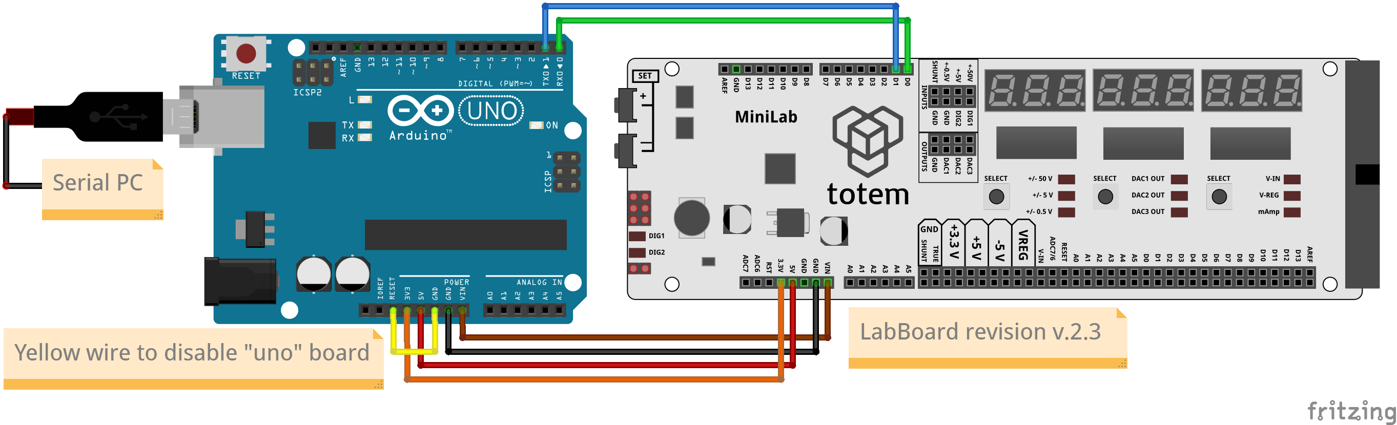
Connect over Arduino board
Direction: PC.
Control: From PC over Arduino board as passthrough.
Power: From Arduino board DC jack or USB.
Flat cable is not connected.
Voltages 3.3V, 5V, VIN are provided by Arduino board. LabBoard does not have voltage regulator (Power scheme).
Required wiring:
- D0 to LabBoard D0
- D1 to LabBoard D1
- 3V3 to LabBoard 3.3V
- 5V to LabBoard 5V
- GND to LabBoard GND
- VIN to LabBoard VIN
- RESET to GND (disable Arduino)
- Select serial mode -
4. SERIAL. - Change value with SET+, SET-. Confirm with Right SELECT.
- Select baud rate (speed) -
bAU 57600.
Select same speed in terminal application. - Select direction -
PC. - Mode is active and displays
Serial.
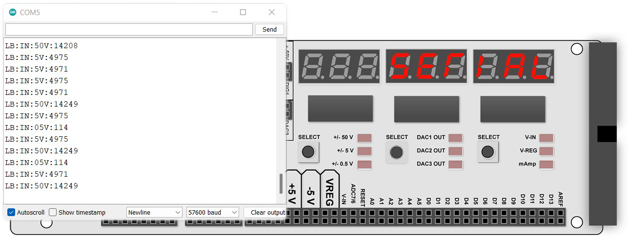
Testing communication with PC:
- Open Arduino IDE, select port, open Serial Monitor.
- Select
57600 baud. - Type in
LB:IN:5V:?, press Enter. - Observe received value
LB:IN:5V:0.
Serial print display
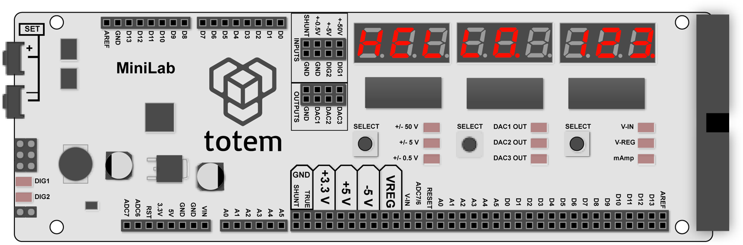
In serial mode (except background) - LabBoard will display data sent using Serial.println() function, acting similar as Arduino IDE Serial Monitor. Because it is limited by showing 9 symbols ant the same moment - it will only display last received line (ending with new line symbol "\n") and aligned to right. Start of longer text will be cut off. It recognizes whole alphabet, but certain letters and symbols are limited by 7 segments.
Example:
Serial.println("Hi");
Serial.print("This");
Serial.print("HELLO.");
Serial.println(" 123.");
Arduino IDE Serial Monitor would print:
Hi
This HELLO. 123.
LabBoard will display only HELLO. 123., because last new line symbol "\n" was sent by Serial.println(" 123."). "This" didn't fit as line of text is aligned to its end. Symbols '.' and ',' are converted to dot segment on display.
It can be disabled with LB.display.setMonitor(false) function or LB:DISP:MON:0. Any data stream not recognized by Serial protocol will be skipped.
Always on (background) mode
In this mode - serial is always enabled to control LabBoard during normal operation (not limited to "4. Serial mode"). This can be used to run LabBoard normally and read measurements externally at the same time.
Note: Serial wiring has to be done according selected endpoint device.
Features "I2C scan" and "AD9833 control" will be disabled on v.2.1, v.2.2 boards if "always on" mode is enabled. SCL pin is occupied with serial communication.
To enable background mode:
- Open menu >
0. SEtUP - Select
5. SERIAL - Click Middle SELECT key to switch between settings.
Change using SET+ SET- keys. - Set default baud rate
bAU 57600 - Set endpoint device -
ArduinoorPC - Set
ALVAYSmode toOn
Serial mode will be active on TX, RX (SCL, DIG2 or D0, D1) pins all the time.