7. AD9833 control
Control AD9833 chip directly from LabBoard. Allows to control output frequency and waveform without requiring to hook up Arduino.
It can be found in Audio side panel ver 3.7.
Setup
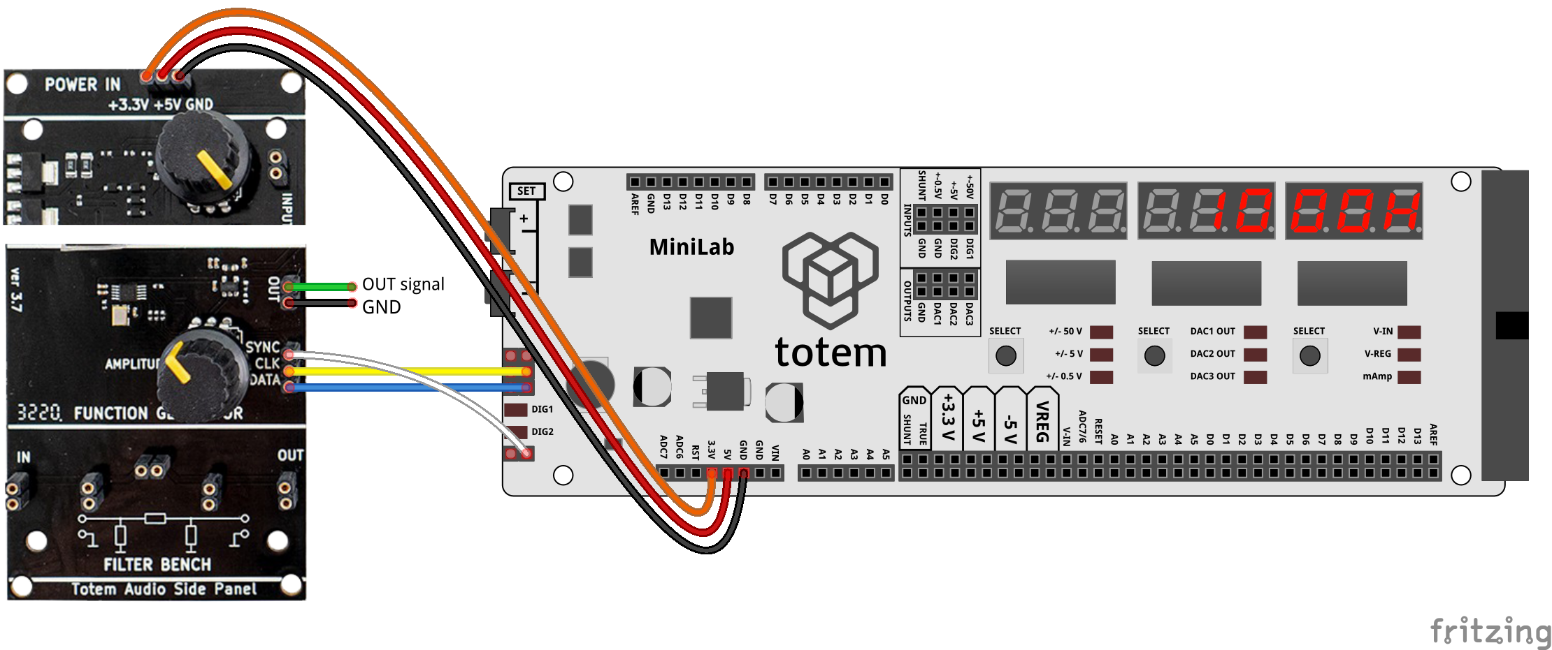
- Hook up power to side panel. Chip requires 3.3V.
- Connect wires:
- +3.3V to LabBoard 3.3V
- +5V to LabBoard 5V
- GND to LabBoard GND
- CLK to LabBoard SCL
- DATA to LabBoard SDA
- SYNC to LabBoard TXD
- Select mode
7. AD9833 - Display will show
1000Hand "OUT signal" pin (green wire) start output 1000 Hz frequency. Lower pins is simply connected to GND.
Control frequency
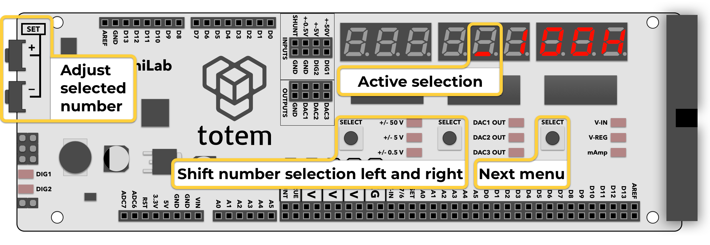
Numerical value can be entered using button combination:
- Left SELECT, Middle SELECT - select digit to edit (indicated by a blinking dot).
- SET+, SET- - change selected digit.
Frequency is updated on value change.
Change waveform
4 different waveforms available:
- Sine
- Triangular
- Square
- Half-Square
Click Right SELECT to switch between waveforms. Pressing other buttons returns back to frequency select.