Audio panel #3
Click image to jump to specific module

Contains:
Arduino examples: Github | TE-SP03-B
This side panel is dedicated for experimenting with signal generation, allowing to visualize and hear its output. It can generate different types of waveforms with configurable frequency. Integrated loudspeaker can be used to listen how signal affects the sound or use external source to play music. Also contains VU meter to visualize signal level in LED bar.
Note: previous side panel version (ver 3.5) contained XR2206 analog signal generator. In (ver 3.7) it has changed to digital AD9833 with addition of filter bench module. Image on the right is older side panel ver 3.5.
Power
On the top of the board there is (POWER IN) pin header to supply power to side panel components. Some of them requires certain voltage to operate, but otherwise they’re fully isolated from one another, and can be used independently.
Side panel requires power (3.3V, 5V, 12V) for certain modules to work. It does not have its own voltage regulator so typically, regulated voltage has to be sourced from TotemDuino or LabBoard. Recommended to plug in all 4 wires as some modules use different voltages. 12V input can accept different voltages. Typically it should be connected to VIN.

Older side panel (ver 3.5) had voltage selector. This was removed in later version 3.7, as it can work with any voltage level.
Audio amplifier + speaker
Contains audio amplifier to boost signal strength from INPUT pin. Amplified signal is routed to OUTPUT pin. Additionally it can be played trough integrated loudspeaker.
Select panel type matching yours:
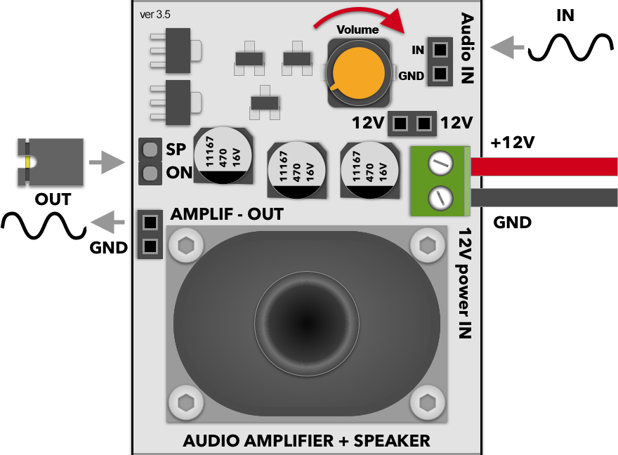
Control:
- Volume - control OUT signal volume (amplitude)
- JP: SP - connect OUT to speaker
Pin header:
- Audio IN: pin 1 - source signal IN
- Audio IN: pin 2 - GND
- OUT: pin 1 - amplified signal OUT
- OUT: pin 2 - GND
- 12V: pin 1, 2 - amplifier power IN
- Screw term. 1 - amplifier power IN (same as pin header)
- Screw term. 2 - GND
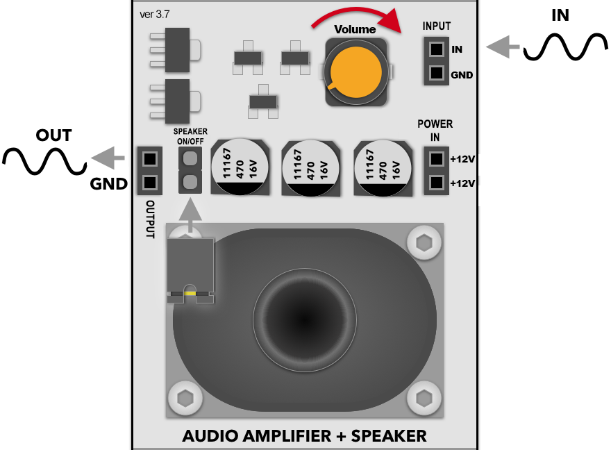
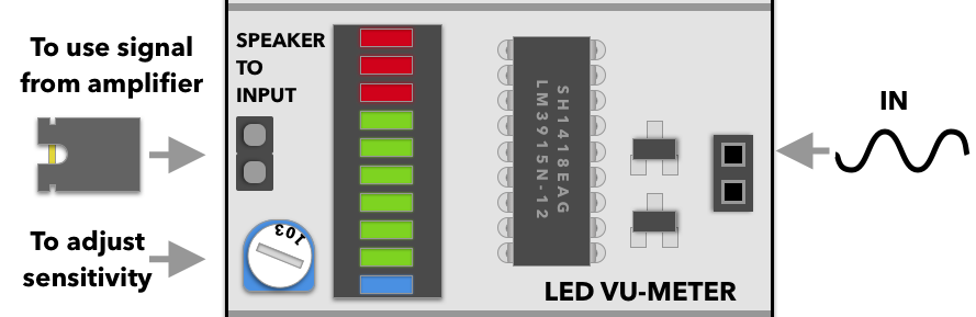
Control:
- Volume - control OUTPUT signal volume (amplitude)
- JP: SPEAKER - connect OUTPUT to speaker
Pin header:
- INPUT: pin 1 - source signal IN
- INPUT: pin 2 - GND
- OUTPUT: pin 1 - amp. signal OUT
- OUTPUT: pin 2 - GND
- +12V: pin 1, 2 - amplifier power IN
Power:
- Uses +12v pin header to power amplification circuit and loudspeaker. Usually should be connected to VIN pin. Voltage can be higher (e.g. 15V).
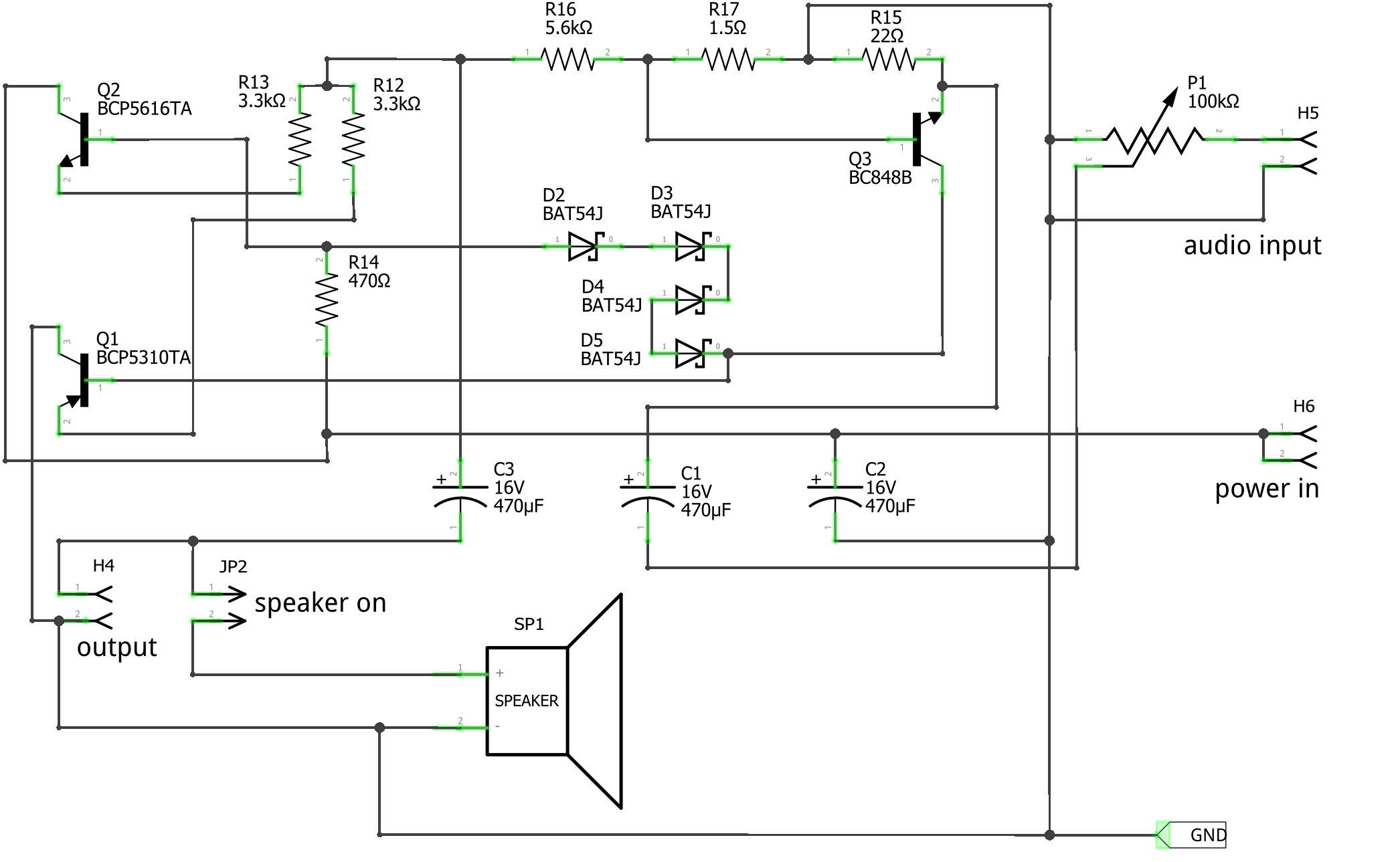
This is an AB class discrete audio amplifier module, capable of up to 1W output RMS power. Input volume is adjusted with potentiometer.
Inbuilt speaker is enabled by connecting SPEAKER ON/OFF jumper, amplified signal output can be connected with a OUTPUT female connector.
You can use the function generator as a signal source (described below) by just connecting a jumper cable between amplifier input and generator output. Another possible input source is using Totem side panel #1 microphone module.
| Schematic | Experiment |
|---|---|
 |
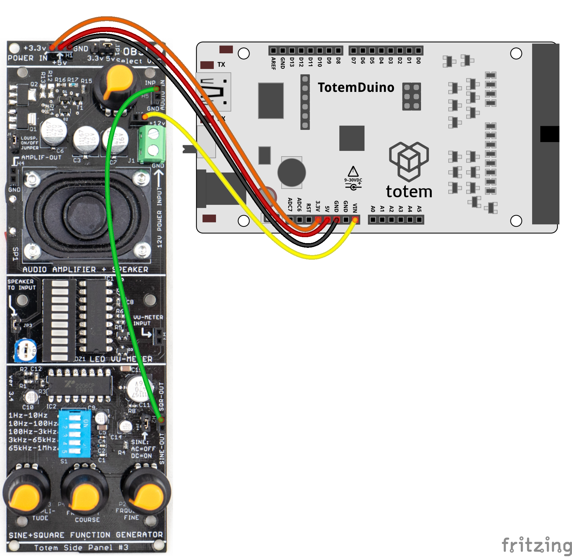 Play generated signal trough loudspeaker. |
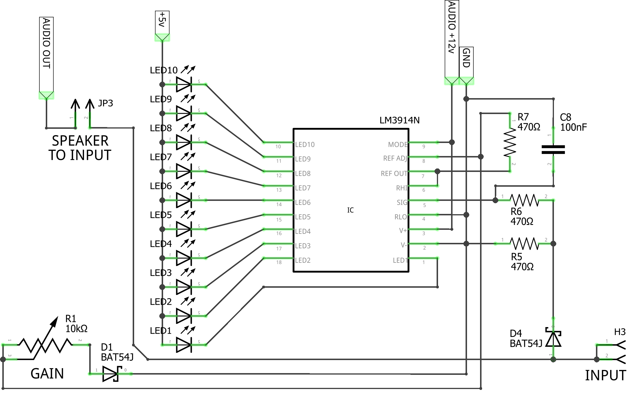
VU Meter
LED bar to visualize input signal Volumetric Unit (VU).
Control:
- Jumper - connect IN to speaker
- Trimpot - adjust sensitivity (gain)
Pin header:
- IN: pin 1, 2 - source signal IN
Power:
- Uses +5V from POWER IN.
- Uses +12v from audio amplifier module input.
An Audio Volumetric Unit (VU) meter module is relying on a 10-bar LED display as an output. Each bar represents a 3dB change in the input signal level. The module shares the same 12 V voltage supply line as the audio amplifier module described above.
Input signal level sensitivity can be adjusted by potentiometer (trimpot). We suggest that before using the module a calibration sequence be performed - apply the maximum allowed input signal to the module, and turn the potentiometer until all LED are lit, except top 3 which are red. During use lit red LEDs will then indicate overload of the input level.
| Schematic | Experiment |
|---|---|
 |
Wire signal generator and visualize its intensity. |
Function generator
Function generator module able to output up to 1Mhz variable frequency signal with different waveform types. Can be used to play different sounds trough loudspeaker or to drive some other circuits.
Select panel type matching yours:
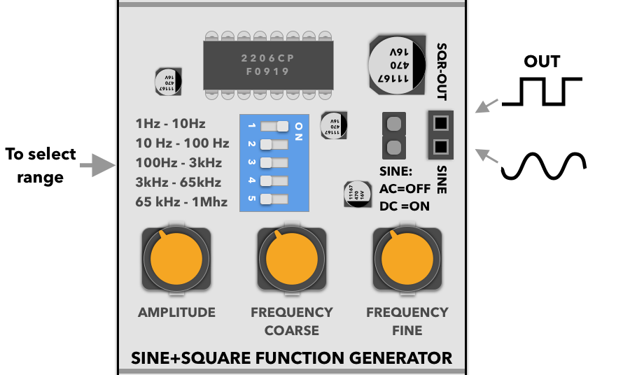
Control:
- DIP switch - select frequency range
- Amplitude - adjust sine amplitude
- Course - adjust frequency
- Fine - adjust frequency (precise)
- SINE: AC/DC - sine wave offset type
Pin header:
- OUT: pin 1 - square signal wave output
- OUT: pin 2 - sine signal wave output
Power:
- Uses VCC power from voltage selector.
- Uses +12v from audio amplifier module input.
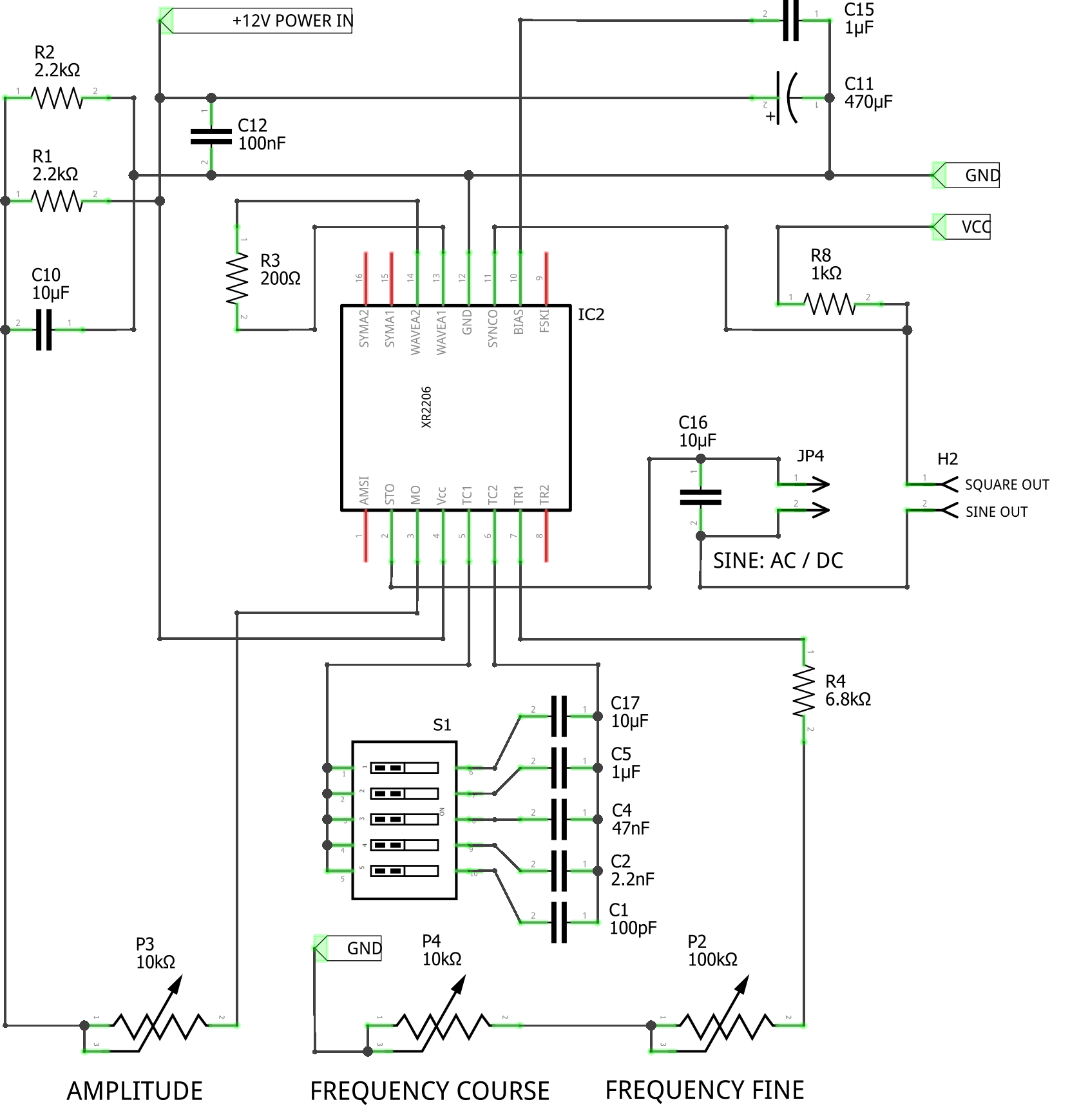
This module contains analog XR2206 chip capable to generate either sine or square wave signals up to 1MHz frequency. Module shares the same 12 V power supply line as the audio amplifier, described above. Frequency range can be changed by sliding switches S1 and further adjusted either in coarse or fine detail with two potentiometer. Sine wave amplitude can be adjusted with a separate potentiometer.
Output sine wave can be selected to be output either with a DC offset, when output is from 0 to VCC with a bias of VCC/ 2, or shifted to AC when the jumper is not connected on the JP4.
Note that only one switch should be active on the S1. We suggest by starting with the range selection, then using coarse adjustment potentiometer to roughly select the desired frequency, and then using fine adjustment potentiometer to fine-tune it.
| Schematic | Experiment |
|---|---|
 |
Play generated signal trough loudspeaker. |
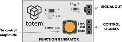
Control:
- Amplitude - adjust signal amplitude
Pin header:
- OUT: pin 1 - signal OUTPUT
- OUT: pin 2 - GND
- SYNC - AD9833 control pin
- CLK - AD9833 control pin
- DATA - AD9833 control pin
Power:
- Uses +3.3V from POWER IN.
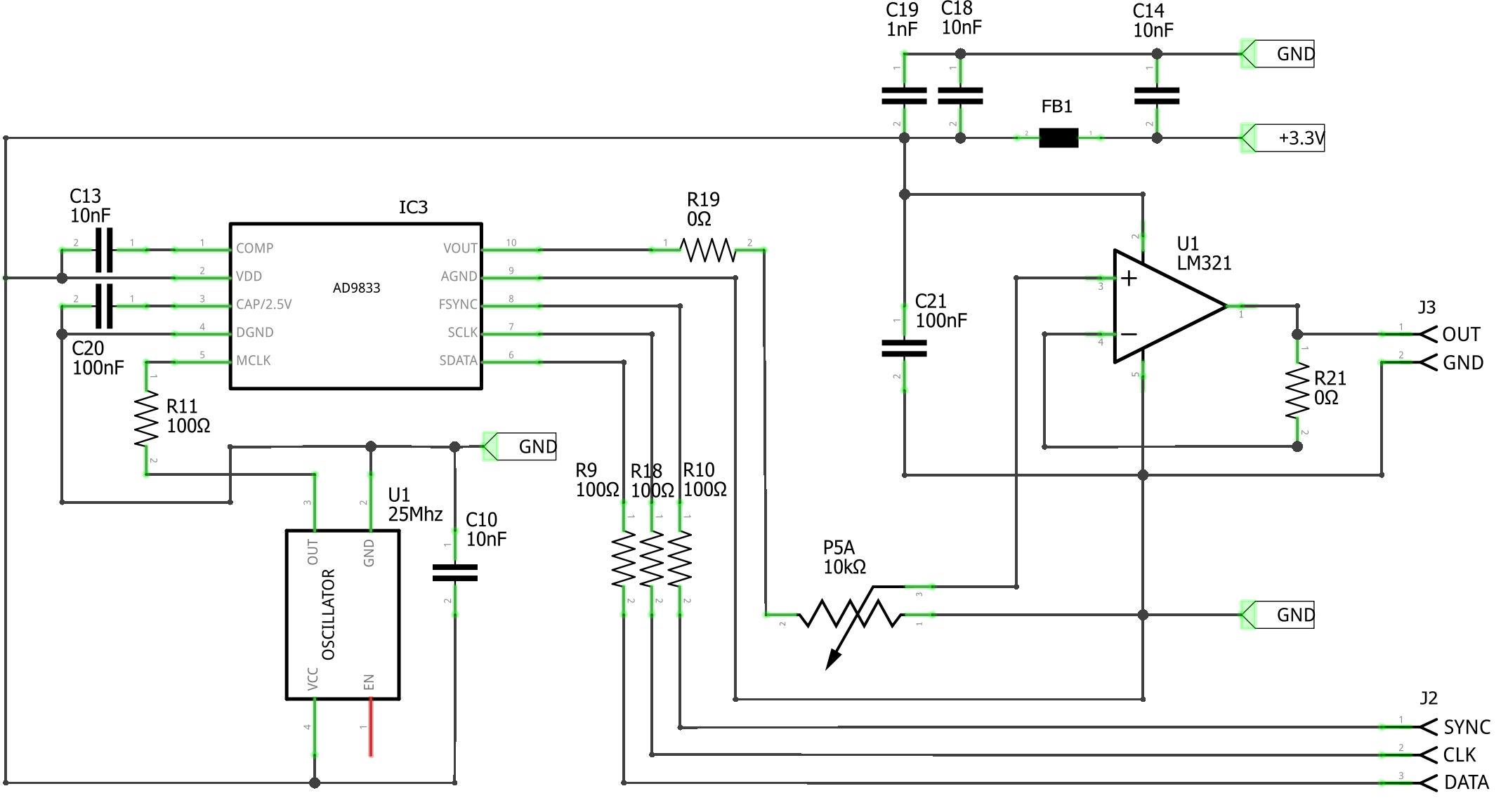
This module contains digital AD9833 chip capable to generate sine, triangle and square wave output signal up to 12.5 MHz frequency. Generated signal is buffered with an operation amplifier, giving the ability to control output signal amplitude. Note that circuit itself is only good for up to around 1Mhz. Higher frequency signals may be unstable or too weak.
LabBoard AD9833 mode can be used to wire and control this chip directly.
Arduino MD_AD9833 library can be used to control this chip from TotemDuino.
Arduino example: Music player.
Arduino example: MIDI interface.
Arduino example: Minimal generator.
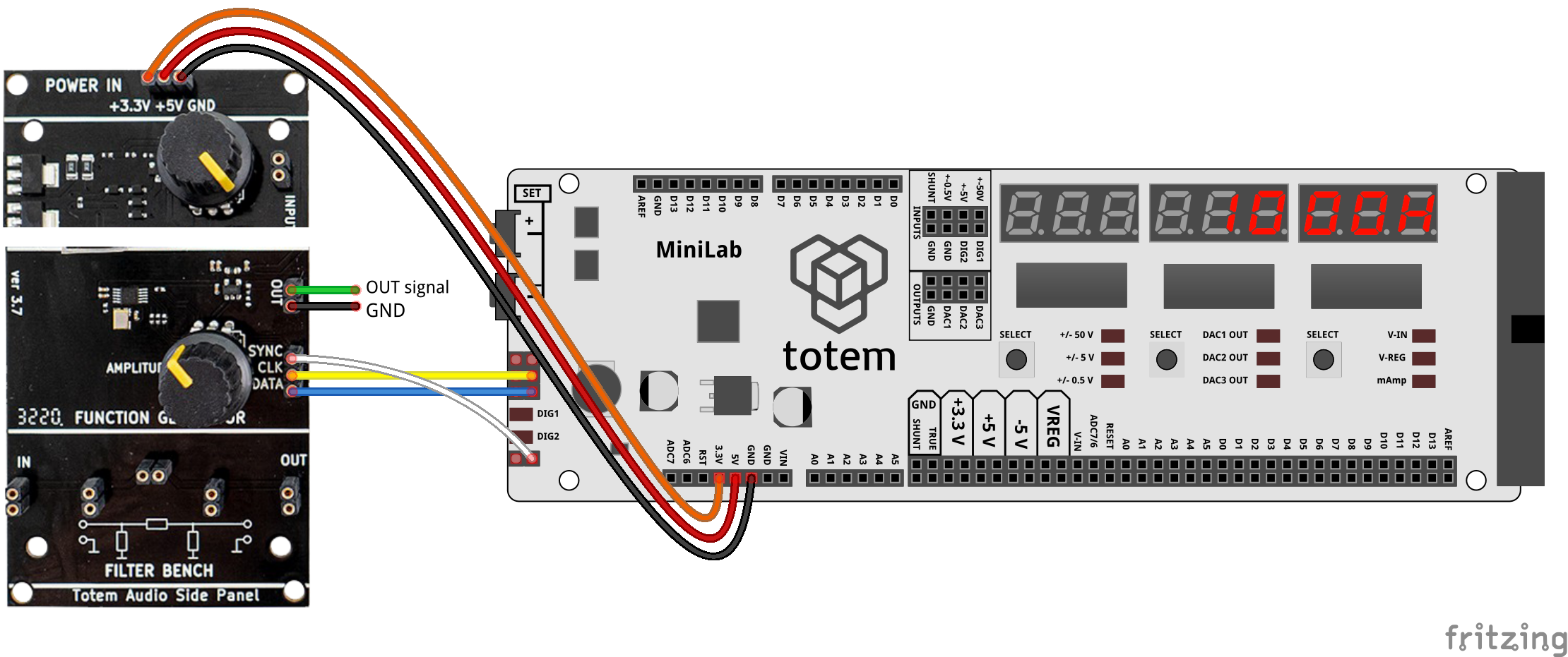
Output of the function generator can be wired to the input of audio amplifier, allowing you to hear the sound of if with no extra parts. Additionally, filter bench module can be placed between those modules to also experiment with pi-filters, and its effect to the signal.
| Schematic | Experiment |
|---|---|
 |
 |
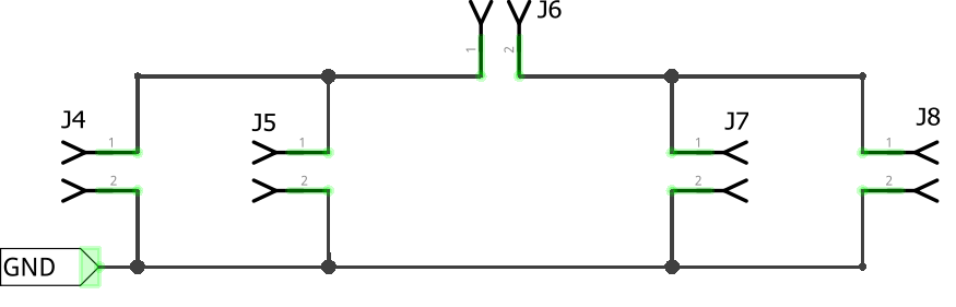
Filter Bench
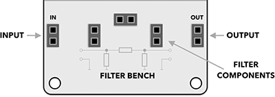
Only available in later panel ver 3.7.
This is a simple framework for experimenting with pi-type filters. It allows you to easily connect different THT components, such as resistors, capacitors and inductors. Filter bench module is meant to be used as middle module between signal generator and audio amplifier modules, allowing user to quickly experience the effect that various components has on the signal.
| Schematic |
|---|
 |
Legacy documentation of #3 Audio side panel:
This page contains latest documentation of audio side panel. Links below are outdated and only specified for reference.
Version 1.0 datasheet (legacy)
Version 1.1 datasheet (legacy)