3. Pulse generator
About
Mode used to generate rectangular waveform with configurable frequency and duty cycle. Can work in infinite mode or output burst of preset number of pulses.
Details
- Output configured signal at TXD pin.
- Inactive TXD pin state - LOW.
- Output voltage is 3.3V (but works with Arduino 5V logic).
- Configurable frequency (period) up to 1 MHz.
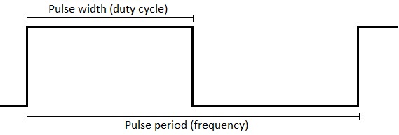
- Configurable duty cycle (pulse width).
- Output continuos signal.
- Output burst of up to 65535 pulses.
- Default settings: 10Hz, 50% duty, 5 cnt burst.
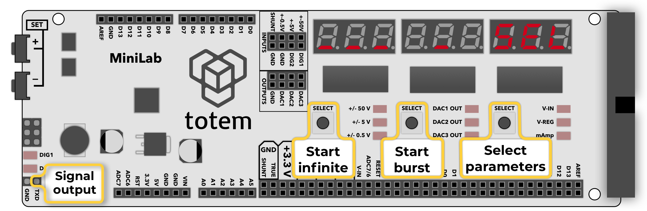
Controls
Consists of 1 main screen to activate signal output and 5 screens to set signal generator parameters.
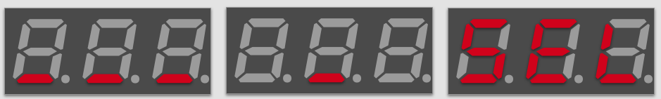
___ _ SEL- main screen. Launch continuos mode | launch burst mode | change settings.10FHZ- configure frequency (Hz).100000FuS- configure frequency in microseconds (µs).50.0d %- configure duty cycle (percentage).50000duS- configure duty cycle in microseconds (µs).5cnt- configure burst count (number).
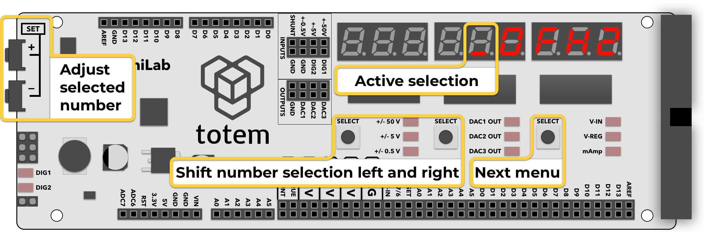
Numerical value can be entered using button combination:
- Left SELECT, Middle SELECT - select digit to edit (indicated by a blinking segment).
- SET+, SET- - change selected digit.
- Right SELECT - jump to next parameter.
Frequency configuration
Signal frequency (pulse period) can be entered in 2 formats:
- hertz: option
FHZ, between1and999999Hz. - microseconds: option
FuS, between1and999999µs.
Entered values are automatically converted between formats.
Changing value updates signal output instantly.
Example: to enter 2000Hz frequency press Right SELECT until FHZ is displayed. Enter number 2000 and go to ___ _ SEL.
Example: to enter 500µs pulse press Right SELECT until FuS is displayed. Enter number 500 and go to ___ _ SEL.
Mathematical relation between hertz and microseconds:
frequency = 1000000 / microseconds
microseconds = 1000000 / frequency
Duty cycle configuration
Signal duty cycle (pulse width) can be entered in 2 formats:
- percentage: option
d %, between0.0and100.0%. - microseconds: option
duS, between0andFuSµs (pulse width can't be higher than period).
Entered values are automatically converted between formats.
Changing value updates signal output instantly.
Example: to enter 23.7% duty cycle press Right SELECT until d % is displayed. Enter number 23.7 and go to ___ _ SEL.
Example: to enter 500µs pulse width press Right SELECT until duS is displayed. Enter number 500 and go to ___ _ SEL.
Mathematical relation between hertz, microseconds and percentage:
frequency = 1000000 / microseconds
microseconds = 1000000 / frequency
microseconds = pulse_period_us * duty_cycle / 100
Duty cycle is a percentage 0..100% of pulse period (frequency). It specifies how long signal is in HIGH state after pulse start.
For example: If we set 400Hz as frequency (2500µs period) and want 35% time HIGH and 65% time LOW, we need to set duty cycle to: 35.0. It means signal will stay HIGH (⎽/⎺) for 875µs and then LOW (⎺\⎽) for 1625µs.
Pulse count configuration
- pulse count: option
cnt, between1and65535.
This mode allows to output burst of pulses (_|⎺|_) when button is pressed.
Only used when Middle SELECT key is clicked in ___ _ SEL screen.
Example waveform of 3 pulse output: ___|⎺|__|⎺|__|⎺|___
Control screen
- Left SELECT - start/stop infinite series of pulse generation with current settings. Once active, this is indicated by series of square symbols.
- Middle SELECT - start/stop finite generation of pulses, making number of pulses entered in pulse count (
cnt). Once finished, indicate value goes back to a single underscore symbol. When active - incrementing percent of pulses emitted, until end. - Right SELECT - (
SEL) go back to configuration.
Enter mode:
- Select Menu >
3. PULSE. - (deprecated) In Main screen hold Left SELECT for 3 seconds.
Exit mode:
- Open menu and select other mode.
Example
- Enter pulse generation mode, select continuous pulse mode with following parameters:
Frequency = 100Hz
Duty cycle = 50% - Enable infinite pulse mode by pressing Left SELECT button.
- Connect TXD pin to an LED.
- Observe that LED lights up. Experiment by changing duty cycle and see that LED dims or brightens. Now you’ve got a working PWM module.