Overview
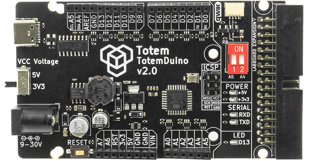
- TotemDuino v2.0

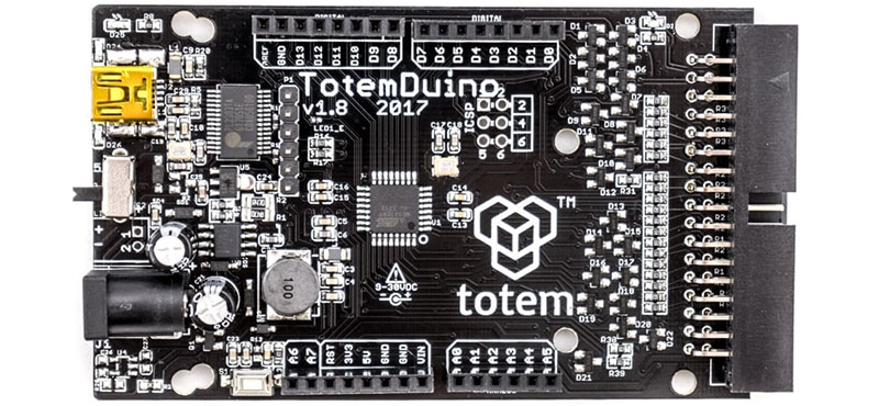
- TotemDuino v1.x

Revision v2.0
New version is released with following improvements:
- Changed USB-Serial chip to CH340 (works with Windows 11)
- Added USB-C, Qwiic (I2C) connector, ICSP header
- Design update, power and serial LED
TE-PR-2
TotemDuino expands upon the great Arduino UNO platform idea. While it is kept fully backwards compatible with Arduino, a lot of additional features are included as well, such as:
- Output protection - comes with all of its output pins going into LabBoard protected against over-voltage or short-circuit conditions.
- Expansion port - a 34 pin flat-cable connection connects to the LabBoard for easy pin access.
- Powerful 5 V regulator - you'll be less likely to run out of power while experimenting with higher power loads such as motors.
- Selectable microcontroller logic voltage - as the world progresses from 5 V towards 3.3 V logic voltage, TotemDuino can work with both just by the flip of a switch, without the need for any additional adapters or converters.
Features
- ATmega328P microcontroller
- 100% Arduino Uno compatible, works with Arduino shields
- Works in Arduino IDE
- 9-30 V DC or 5V USB supply power range
- Selectable 5V or 3.3V logic voltage
- Noise immune design
- Additional filtering for precise analog voltage measurements
- Integrated programmer - no extra parts needed to start coding.
- Arduino and Totem compatible mounting holes
- 34-pin flat cable connector for integration with Totem Mini Lab
Layout

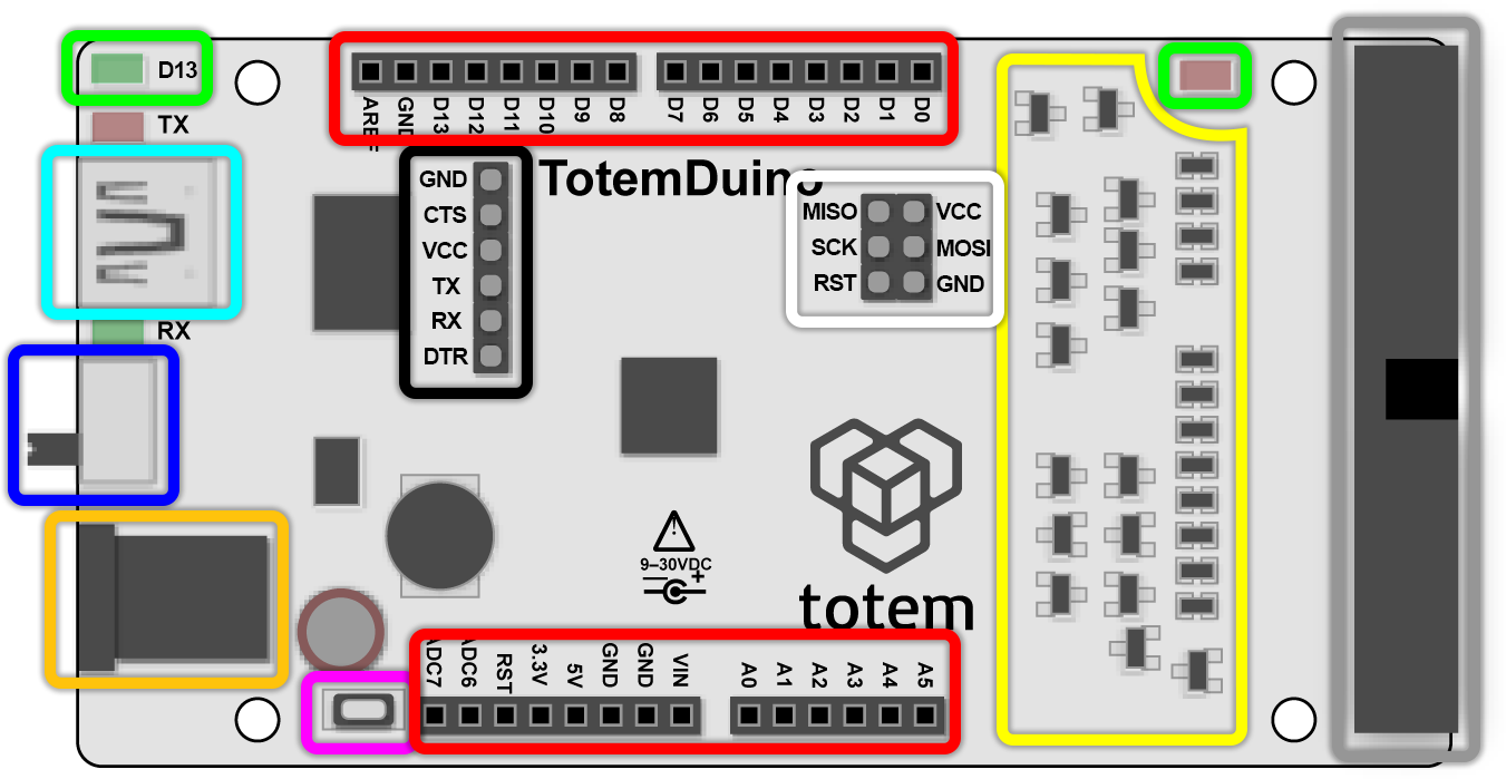
- Arduino pin headers - programmable pin headers of ATmega328P processor.
D- digital,A- analog, others - power supply. Layout is compatible with Arduino Uno form factor and shields. - LED - LED on the right indicates if TotemDuino is powered on.
LED D13 displays state of D13 pin. Can be used with classical blinking example:
void setup() { pinMode(13, OUTPUT); } void loop() { digitalWrite(13, HIGH); // turn the LED on (HIGH is the voltage level) delay(1000); // wait for a second digitalWrite(13, LOW); // turn the LED off by making the voltage LOW delay(1000); // wait for a second } - Voltage switch - Switch to select between 3.3V (down) or 5V (up) logic level. Processor will function on the selected voltage. Standard Arduino (ATmega328P) boards always works on 5V logic level. This is convenient if you need to connect sensors that are 3.3V only (could be damaged if using with 5V).
- Reset button - reset processor. Will restart running sketch. Same as connecting RST to GND.
- Protection circuit - pin protection circuit for over-voltage or short-circuit conditions.
- USB input - allows to connect TotemDuino to PC. Used for power (if DC not connected), programming (sketch upload), print messages (Serial Monitor).
- DC input - provides power for TotemDuino (and Mini Lab). Center positive. Can accept voltages between 9-30VDC. Directly routed to VIN pin. Used to create regulated 3.3V and 5V.
- Flat cable - port to connect TotemDuino with LabBoard. It routes power and all Arduino pin headers to LabBoard.
- Serial header - header of USB-Serial converter output. Not used.
- ICSP header - standard pins for In Circuit Serial Programming. Not used and header is not soldered.
- Qwiic connector - Connect external I2C modules. Pull white switches to ON position in order to connect A4, A5 pins to connector (board v2.0 only).