Serial protocol
Serial protocol to control LabBoard from Arduino or external device, like PC.
Command must start with LB prefix, separated by :, ending with new line symbol \n.
Example: Serial.print("LB:OUT:DAC1:1500\n") or Serial.println("LB:OUT:DAC1:1500")
Protocol:
| Command | Description |
|---|---|
LB:<group>:<cmd>:<value> |
Write value to specific command |
LB:<group>:<cmd>:? |
Request to read specific command |
LB:<group>:? |
Request to read all commands in group |
LB:? |
Request to read all LabBoard commands |
LB:<group>:<cmd>:! |
Enable notify for specific command. !0 - disable |
LB:<group>:! |
Enable notify for all commands in group. !0 - disable |
LB:! |
Enable notify for all LabBoard commands. !0 - disable |
Examples:
Calling LB:OUT:DAC1:1500 will change DAC1 output to 1.5 Volts.
Calling LB:OUT:DAC1:? will return current value of DAC1 - LB:OUT:DAC1:1500.
Calling LB:IN:? will return of all 5 "Voltage input" commands with values.
Calling LB:IN:5V:! will stream LB:IN:5V:1000 value on each change.
Voltage input
Read voltage of VIN, ±50V, ±5V, ±0.5V pins and current of SHUNT pin.
| Command | Parameter | Description |
|---|---|---|
LB:IN:VIN: |
6000 - 30000 mV |
VIN pin voltage |
LB:IN:50V: |
-50000 - 50000 mV |
±50V pin voltage |
LB:IN:5V: |
-6150 - 6150 mV |
±5V pin voltage |
LB:IN:05V: |
-700 - 700 mV |
±0.5V pin voltage |
LB:IN:AMP: |
0 - 800 mA |
SHUNT pin current |
LB:IN:50V and LB:IN:05V limits can vary a bit.
Read instructions how to setup current measurement.
-100000 is returned if measurement is invalid or over the limit.
Channel overvoltage may invalidate measurements of other channels also.
Voltage output
Set voltage to VREG, DAC1, DAC2, DAC3 pins.
| Command | Parameter | Description |
|---|---|---|
LB:OUT:VREG: |
3000 - VIN - 1000 mV |
VREG pin voltage |
LB:OUT:DAC1: |
0 - 3250 mV |
DAC1 pin voltage |
LB:OUT:DAC2: |
0 - 3250 mV |
DAC2 pin voltage |
LB:OUT:DAC3: |
0 - 3250 mV |
DAC3 pin voltage |
LB:OUT:VREG maximum voltage depends on VIN voltage, which is 15V with provided DC power supply. In this case, output range is - 3000 - 14000 mV.
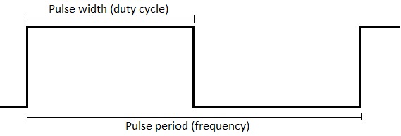
Frequency generator
Output configurable Pulse-width modulation to TXD pin.
| Command | Parameter | Description |
|---|---|---|
LB:TXD:RUN: |
0 - stop 1 - start TXD 2 - start TXD burst |
Generator control |
LB:TXD:FHZ: |
1 - 1000000 Hz |
Frequency in hertz |
LB:TXD:FUS: |
1 - 1000000 μs |
Frequency in microseconds |
LB:TXD:DUS: |
0 - 1000000 μs |
Duty cycle in microseconds |
LB:TXD:DPCT: |
0 - 1000 % |
Duty cycle percentage (% * 10) |
LB:TXD:CNT: |
0 - 65535 |
Pulses count in burst mode |
LB:TXD:FHZ is tied to LB:TXD:FUS. Both control output frequency but with different units.
LB:TXD:DUS is tied to LB:TXD:DPCT. Both control output duty cycle but with different units.
LB:TXD:DUS maximum value is limited by LB:TXD:FUS. Pulse width can't be longer than Period.
LB:TXD:DPCT is percentage multiplied by 10 for more precision.
LB:TXD:CNT is a number of pulses to generate when calling command LB:TXD:RUN:2.
Frequency monitor
Measure frequency with DIG1 pin.
| Command | Parameter | Description |
|---|---|---|
LB:RXD:RUN: |
0 - disable RXD 1 - enable RXD |
Monitor control |
LB:RXD:EDGE: |
0 - LOW edge 1 - HIGH edge |
Sample (detect) edge. Default: HIGH |
LB:RXD:CNT: |
write: 0 - reset to 0 read: pulses count |
Number of pulses |
LB:RXD:FHZ: |
read: 0 - 23000000 hertz |
Measured frequency |
Digital inputs
Read state of digital DIG1 and DIG2 pins.
| Command | Parameter | Description |
|---|---|---|
LB:DIG1: |
0 - LOW 1 - HIGH |
Digital pin state |
LB:DIG2: |
0 - LOW 1 - HIGH |
Digital pin state |
Display control
| Command | Parameter | Description |
|---|---|---|
LB:DISP:TXT:<text> |
string | Put text on display (align left) |
LB:DISP:TXT:<seg>:<text> |
<seg> : 0 - 8 <text> : string |
Put text on display (offset from left) |
LB:DISP:DIM: |
0 - 15 |
Display brightness |
LB:DISP:BLI:<rate> |
<rate> : milliseconds |
Display blink rate |
LB:DISP:BLI:<hex>:<rate> |
<hex> : HEX value 0 - 1FF<rate> : milliseconds |
Display segment blink rate |
LB:DISP:MON: |
0 - disabled 1 - enabled |
Serial monitor mode Default: enabled |
<text> is a string of 9 characters. Symbols . , will use dot segment. Example: DISP 4.567.
<hex> is map of segments that will be affected. There are 9 segments, starting at from left.
<rate> is blinking frequency in milliseconds. Setting 0 will disable blinking.
LB:DISP:MON is a feature to print Serial.println() content to display in 4. SERIAL mode.
Key press
Read currently pressed LabBoard keys.
| Command | Parameter | Description |
|---|---|---|
LB:KEY:<hex> |
<hex>: HEX value 0 - 1F |
Binary map of pressed keys |
<hex>:
B00001 - SET-
B00010 - SET+
B00100 - Right SELECT
B01000 - Middle SELECT
B10000 - Left SELECT
LB:KEY returns HEXdecimal value. Example: LB:KEY:C converts to B01100. This means that keys Right SELECT and Middle SELECT are currently pressed.
LED control
Control individual LabBoard LED.
| Command | Parameter | Description |
|---|---|---|
LB:LED:<hex> |
<hex>: HEX value 0 - 7FF |
Binary map of LED state |
LB:LED:<num>:<state> |
<num>: LED number 1 - 11 <state>: 0 - off, 1 - on |
State of specific LED |
LED names
| Number | Name on board | Binary map |
|---|---|---|
| 0 | All | B00000000000 |
| 1 | DIG1 | B00000000001 |
| 2 | DIG2 | B00000000010 |
| 3 | ±50V | B00000000100 |
| 4 | ±5V | B00000001000 |
| 5 | ±0.5V | B00000010000 |
| 6 | DAC1 | B00000100000 |
| 7 | DAC2 | B00001000000 |
| 8 | DAC3 | B00010000000 |
| 9 | VIN | B00100000000 |
| 10 | VREG | B01000000000 |
| 11 | mAmp | B10000000000 |
<hex> is binary map on turned on LEDs.
<num> is number of LED in a list from DIG1 to mAmp. Starting at digit 1 to 11. 0 - all.
<state> is state of LED. 0 - lit off, 1 - lit on.
Example: command LB:LED:2C will turn on ±50V, ±5V and DAC1. All other - off.
Example: command LB:LED:10:1 will turn on mAmp. Does not change other LED.
Configuration
Control LabBoard settings.
| Command | Parameter | Description |
|---|---|---|
LB:CFG:REV: |
22 23 |
Revision number |
LB:CFG:VER: |
200 |
Firmware version |
LB:CFG:SBAUD: |
57600 |
Default serial baud rate |
LB:CFG:SMODE: |
0 - PC 1 - Arduino |
Default serial mode Default: Arduino |
LB:CFG:SON: |
0 - off 1 - on |
Background serial mode Default: off |
LB:CFG:DISP: |
7 |
Display brightness |
LB:CFG:VREG: |
0 |
Calibration offset |
LB:CFG:DAC1: |
0 |
Calibration offset |
LB:CFG:DAC2: |
0 |
Calibration offset |
LB:CFG:DAC3: |
0 |
Calibration offset |
LB:CFG:VIN: |
0 |
Calibration offset |
LB:CFG:50V: |
0 |
Calibration offset |
LB:CFG:5V: |
0 |
Calibration offset |
LB:CFG:05V: |
0 |
Calibration offset |
LB:CFG:RST: |
1 |
Reset all configuration Restart required after. |
LB:CFG:REV is board revision number. v.2.1 and v.2.2 both returns 22.
LB:CFG:VER is firmware version number. 250 converts to 2.50.
LB:CFG:DISP is default display brightness. Value between 0 and 15.
Calibration offset is a drift from correct measurement in mV. Can be negative.
System control
| Command | Parameter | Description |
|---|---|---|
LB:BOOT: |
1 |
Restart in boot mode |
LB:RST: |
1 |
Restart LabBoard |
Boot mode is used during firmware update.